What is basic BGP community concept?
This instruction is good reference. In fact, I will analysis this instruction. BGP community is used for filtering and tagging information over routing information. Therefore, routing table information will be controlled by these condistions. Thus I can select the routing information to advertise or update in the table.
1. Pre-requiste (Basic BGP configuration)
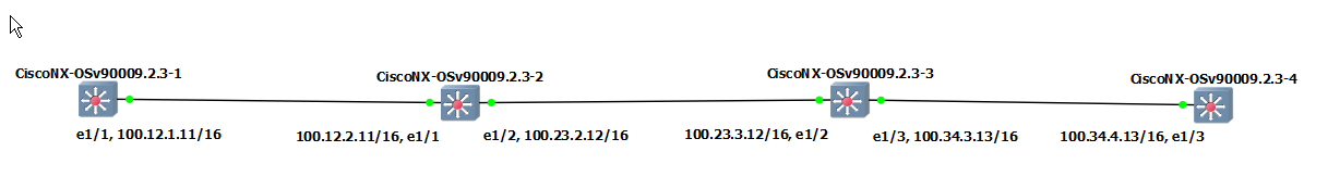
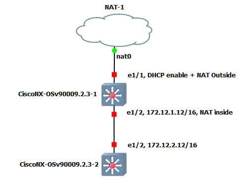
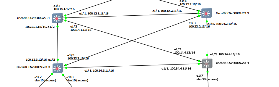
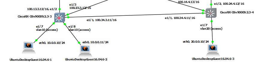
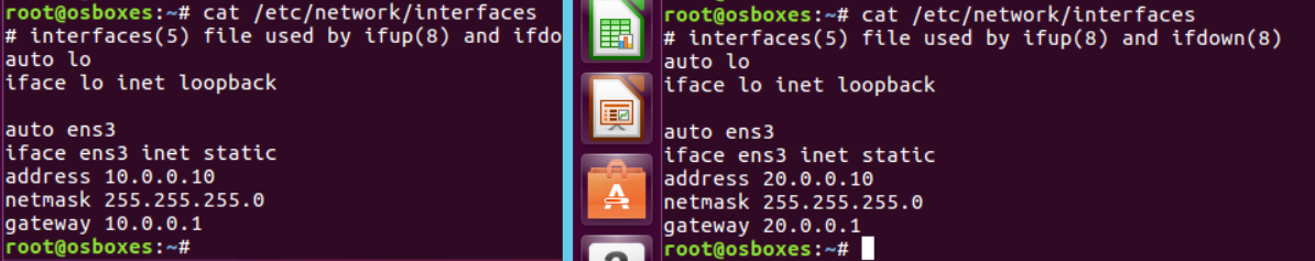
This is my environment for this post.
| S1 | S2 | S3 | S4 |
|
interface Ethernet1/1 no switchport ip address 100.12.1.11/16 no shutdown ! interface loopback0 ip address 1.1.1.1/32 ! interface loopback1 ip address 11.11.11.11/32 ! router bgp 1 router-id 1.1.1.1 log-neighbor-changes address-family ipv4 unicast network 1.1.1.1/32 network 11.11.11.11/32 neighbor 100.12.2.11 remote-as 2 update-source Ethernet1/1 address-family ipv4 unicast |
interface Ethernet1/1 no switchport ip address 100.12.2.11/16 no shutdown interface Ethernet1/2 no switchport ip address 100.23.2.12/16 no shutdown ! interface loopback0 ip address 2.2.2.2/32 ! interface loopback1 ip address 22.22.22.22/32 ! router bgp 2 router-id 2.2.2.2 log-neighbor-changes address-family ipv4 unicast network 2.2.2.2/32 network 22.22.22.22/32 neighbor 100.12.1.11 remote-as 1 update-source Ethernet1/1 address-family ipv4 unicast neighbor 100.23.3.12 remote-as 3 update-source Ethernet1/2 address-family ipv4 unicast |
interface Ethernet1/2 no switchport ip address 100.23.3.12/16 no shutdown interface Ethernet1/3 no switchport ip address 100.34.3.13/16 no shutdown ! interface loopback0 ip address 3.3.3.3/32 ! interface loopback1 ip address 33.33.33.33/32 ! router bgp 3 router-id 3.3.3.3 log-neighbor-changes address-family ipv4 unicast network 3.3.3.3/32 network 33.33.33.33/32 neighbor 100.23.2.12 remote-as 2 update-source Ethernet1/2 address-family ipv4 unicast neighbor 100.34.4.13 remote-as 4 update-source Ethernet1/3 address-family ipv4 unicast |
interface Ethernet1/3 no switchport ip address 100.34.4.13/16 no shutdown ! interface loopback0 ip address 4.4.4.4/32 ! interface loopback1 ip address 44.44.44.44/32 ! router bgp 4 router-id 4.4.4.4 log-neighbor-changes address-family ipv4 unicast network 4.4.4.4/32 network 44.44.44.44/32 neighbor 100.34.3.13 remote-as 3 update-source Ethernet1/3 address-family ipv4 unicast |
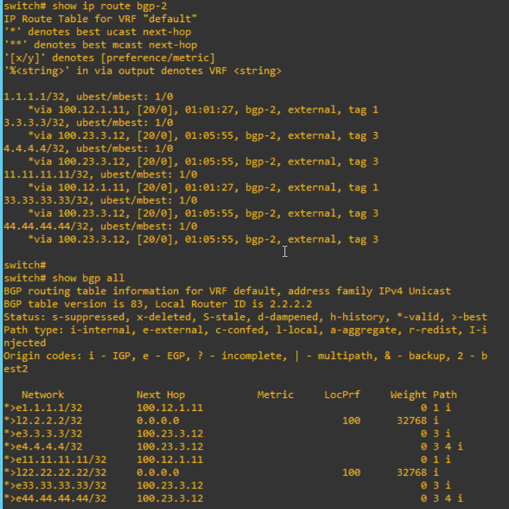
For nexus, "address-family ipv4 unicast" in neighbor parameter and "address-familiy ipv4 unicast" in global parameter are necessary to advertise to the peer. After configure these, I can verify the routing table and BGP information. From S2,
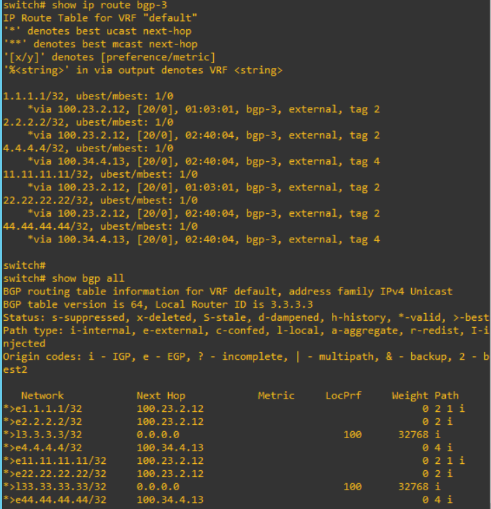
From S3,
From S4,
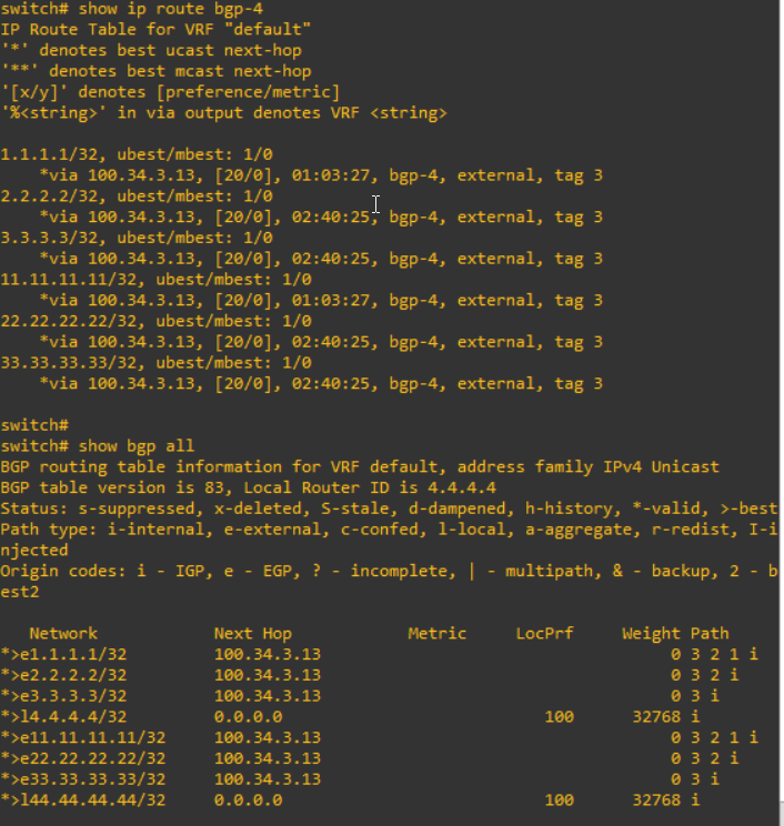
I can confirm that the information from S1 such as "1.1.1.1" and "11.11.11.11" are advertised to S2, S3 and S4.
2. Configure send community
To use the BGP community, I have to configure "send community". There are 2 types, standard and extended. In this struction, the extended community has more information such as VPN services.

I will added the configuration like below.
| S1 | S2 | S3 | S4 |
|
router bgp 1 neighbor 100.12.2.11 address-family ipv4 unicast send-community both |
router bgp 2 neighbor 100.12.1.11 address-family ipv4 unicast send-community both neighbor 100.23.3.12 address-family ipv4 unicast send-community both |
router bgp 3 neighbor 100.23.2.12 address-family ipv4 unicast send-community both neighbor 100.34.4.13 address-family ipv4 unicast send-community both |
router bgp 4 neighbor 100.34.3.13 address-family ipv4 unicast send-community both |
Please note that there are any differences of routing table after these configuration above.
3. Configure Route-map in and out
To use the BGP community, the route-map is necessary. This route-map affect the routing table. In S3, I will add "route-map" configuration.
|
! router bgp 1 neighbor 100.12.2.11 address-family ipv4 unicast route-map to-remote-as2 out end ! |
"route-map to-remote-as2 out" mean that routing information to transfer out will be controlled with this route-map. Therefore, after this configuration, the routing table will be changed. "1.1.1.1" and "11.11.11.11" are removed.

Now, I will add the policy to set community.
|
ip prefix-list ip-prefix-1 seq 10 permit 1.1.1.1/32 |
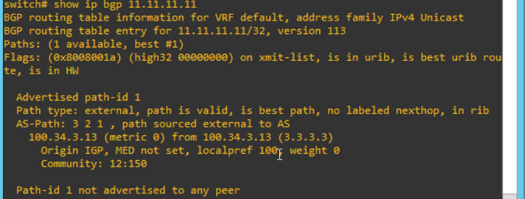
I check the routing table from S4. "1.1.1.1" and "11.11.11.11" will be updated.

And I can see more detail. I can see the community values are changed on each.

So far, I learn how to set the community with BGP. From now, I will handle how to get the community and use this. This is so similar with above. I will add configure into the S2.
|
! router bgp 2 neighbor 100.12.1.11 address-family ipv4 unicast route-map from-remote-as1 in end ! |
After configure this, the routing table will be changed. "1.1.1.1" and "11.11.11.11" are removed again.

Now, I will add some configuration to get community and use it in S2.
|
ip community-list expanded community-1 seq 1 permit "12:130" ip community-list expanded community-2 seq 1 permit "12:150" route-map from-remote-as1 permit 10 match community community-1 set local-preference 130 route-map from-remote-as1 permit 20 match community community-2 set local-preference 150 |
These configuration effect S2 routing table like below.
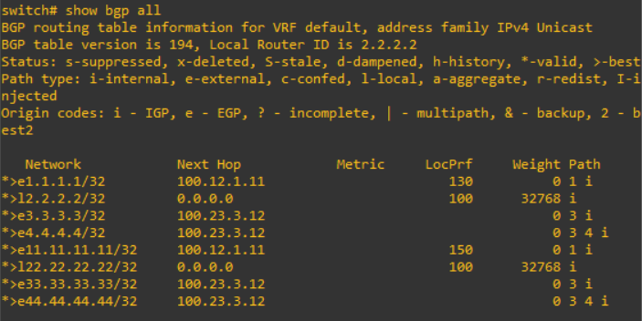
However, it does not effect S3 and S4, even if the community value is left.

Reference
[ 1 ] https://www.cisco.com/c/en/us/support/docs/ip/border-gateway-protocol-bgp/28784-bgp-community.html
[ 2 ] http://www.ciscopress.com/articles/article.asp?p=2756480&seqNum=12
[ 3 ] https://blog.naver.com/happy_jhyo/221291791846
'Network Engineering > Basic Learning' 카테고리의 다른 글
| How does the OSPF cost work? (0) | 2019.07.18 |
|---|---|
| How to work BGP synchronize and next hop self with Nexus? (0) | 2019.07.11 |
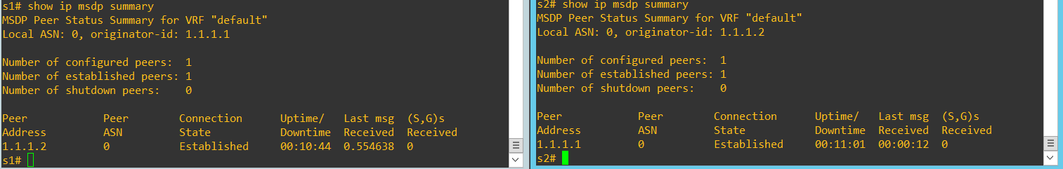
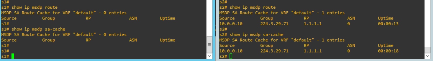
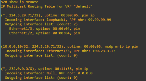
| How does the multicast (PIM sparse mode) work with MSDP? (0) | 2019.06.07 |
| How SSL/TLS handshake can be done? (0) | 2018.12.18 |
| How to calculate sequence number of the TCP/IP packets? (0) | 2018.12.17 |