Window size value : This is the value to receive from other side. (Window size is advertising the RCV buffer space available for the device, how much memory is allocated for the session)


The maximum field for TCP window size = 65535 or 0xFFFF because it is a 2 byte field.  There is a method to make it bigger by negotiating the window using the scaling option. 


I can see in the SYN packet option – Window Scale = 7.  This tells the server it wants to use this option and multiply the window size by 128. And Server agree in the SYN+ACK with the same option = 7.  This tells the client it also will be using the scaling option.

Window scale number 7 means that 2^7 = 128. This number is never changed until fininshing converstation.


After this negotiation, I can look at packet 3 in the TCP section at the Window you will see it shows (211 x 128 = 27008) 

From Server, I can see the window scale option is enabled like below


And middle of the packets, I can see the widnow size more than 65535. 76288 is the sample to use scale option. 


This is normal case to show how the scale option is used.


[Without Window scaling option Case]


This is the sample case to show what the window scale dose not work. In the first syn packet, there is the option. However the syn-ack paket does not have this option like below.

This below is syn-ack packet. There is no window scale option.

So, the last ack packet decide to send packet without the window scale option.

In wireshark, -2 mean that there is no window scale option definition. Please note that -2 always means "no window scale option". If there is no packet syn, syn-ack and ack due to capturing middle of packets, the wireshark determind -2 even if the window size is more than 65535.


Sometimes, I need to see the packet with wireshark tool. I have to calculate sequence numbers. I have learned the IP packet size is 1540 (MSS is 1460). However, I can see the more size in the packet. This post is good for me.


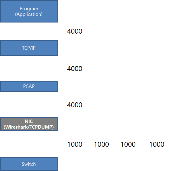
This is whole diagram to understand my situation. This is the reason why I need to capture the packet with switch port.


Please look at the first Syn packet. There is MSS is 8961. In blow, I wrote the MSS size is 1460. However, the wireshark show more than 8961. 


How to calculate sequence number of the TCP/IP packets?

How to calculate sequence number of the TCP/IP packets? I am the network engineer. Recently, I have some change to remember the sequence number of the TCP/IP packets. Someone include me think that t..

createnetech.tistory.com

Thus, this is not perfect number. 


[ Reference ]

[ 1 ] https://packetbomb.com/how-can-the-packet-size-be-greater-than-the-mtu/

[ 2 ] https://createnetech.tistory.com/25?category=672583


1. Simple OSPF Parameters to Use

Before configuring the OSPF, I will handle some concept necessary to configure. For interface configuration, there is some term of network type. In this blog, those are compared simply.

In the above, DR/BDR terms are shown. If you did not study about the OSPF, it is not easy. DR has the role to share the OSPF information between the routers and switches. In this blog, it show simple diagram to explain about these.

DR make simple to share routing table information. Because of this, it is useful in Broadcast network. Howerver, I confuse about the Point to Multipoint concept. It looks like Broadcast. I refers this blog. It is different I need to annount the neighbor IP address with "Neighbor" or "Frame-relay" options.


2. Unnumbered Interfaces | net.ipv4.conf.<interface name>.rp_filter value=0

In fact, I did not realize this concept. I met the error message "Please remove network command first" during configure OSPF with FRR. In this post, there are some explain about this.

Unnumberd Interface improve the performance. I need to edit "net.ipv4.conf.<interface name>.rp_filter value=0" in the "/etc/sysctl.conf"

Because of this "unnumbered interface existance", FRRouting give some limitation. After network definition in router ospf part, I can not activate the interface for OSPF.


Reference

[ 1 ] https://docs.cumulusnetworks.com/cumulus-linux-37/Layer-3/Open-Shortest-Path-First-OSPF/

[ 2 ] https://www.freeccnaworkbook.com/workbooks/ccna/configuring-ospf-network-types

[ 3 ] https://www.fir3net.com/Networking/Protocols/ospf-the-dr-and-bdr-roles.html

[ 4 ] https://packetlife.net/blog/2008/jun/19/ospf-network-types/

[ 5 ] http://www.getnetworking.net/tutorials/ospf-point-to-multipoint-over-frame-relay

[ 11 ] https://www.cisco.com/c/en/us/td/docs/ios-xml/ios/iproute_ospf/configuration/xe-16/iro-xe-16-book/iro-cfg.html

A few years ago, I have read about Quagga. It is software router which can install on the Linux such as Ubuntu. I have heard about this FRRouting which is next generation of the Quagga. In this post, I will configure some feature from FRRouting.


1. Installation

I will use Ubuntu 18.04. In this instruction, there are steps to install for Debian Linux. 

By the instruction, It will be work. 

After installation, I can check the the directory created in "/etc/frr/" like below.


2. Crash Log File.

This is the directory, "/var/tmp/frr/<daemon>[-<instance>].<pid>/crashlog" which I have refer.


3. Daemon Configuration.

After I start the FRR with "/etc/init.d/frr start" command, I can check the listen Port. I can see "staticd" and "zebra" daemon are loaded. This is the basic daemon.

When I want to more routing protocol, there are 2 things necessary, configuration file such as bgpd.conf and activate the protocol. 

The configuration sample files are located under the "/usr/share/doc/frr/examples/zebra.conf.sample". (Please not that those file has ownership by "frr". Thus I need to update with "chown frr.frr zebra.conf".)

When I handle the Quagga at first time, There are something difficult to use it. It is "Intergrated-vtysh-config". I need each configuration file to load each routing protocol. This means that I have to edit each file.

I think that FRR improve this part rather than before. Please read this. there are "frr.conf" file.

If this file "frr.conf" is existed, each configuration file will not be loaded. I have to remove "frr.conf" to load each file.

4. How to save configurartion file on VTY Shell mode.

In FRR, VTY Shell (Intergrated mode) is useful. However, there are something import. Basically, the routing protocol works on each daemon with each configuration file. It is not simple to load from common configuration file "frr.conf" to each daemon. This relationship make some consideration about the save file.

I configure "service intergrated-vtysh-config" in frr.conf and try to save with "write intergrated" insted "write file"

4. Enable BGP Feature of FRRouting

In "/etc/frr/daemon" filel there is the step to define the protocol what I want. In my case, I will active BGP Protocol It looks like below.

root@ip-10-10-0-134:~# cat /etc/frr/daemons   
bgpd=yes
ospfd=no
ospf6d=no 

At this time, I only activate BGP Protocol.


5. Configure Internal BGP with Route Reflector.

In this post, I handle similar environment with bird opensource. I think it will be good comparison. This .


Host #1 (Top) Host #2 (Left side of Bottom) Host #3 (Right side of Bottom)
ip-10-10-0-64# show running-config 
Building configuration...

Current configuration:
!
frr version 7.3
frr defaults traditional
hostname ip-10-10-0-64
log syslog informational
no ipv6 forwarding
service integrated-vtysh-config
!
router bgp 65001
 bgp router-id 10.10.0.64
 neighbor 10.10.0.107 remote-as 65001
 neighbor 10.10.0.134 remote-as 65001
 !
 address-family ipv4 unicast
  neighbor 10.10.0.107 route-reflector-client
  neighbor 10.10.0.134 route-reflector-client
 exit-address-family
!
line vty
!
end
ip-10-10-0-107# show running-config 
Building configuration...

Current configuration:
!
frr version 7.3
frr defaults traditional
hostname ip-10-10-0-107
log syslog informational
no ipv6 forwarding
service integrated-vtysh-config
!
interface lo
 ip address 1.1.1.1/32
 ip address 1.1.1.2/32
!
router bgp 65001
 bgp router-id 10.10.0.107
 neighbor 10.10.0.64 remote-as 65001
 !
 address-family ipv4 unicast
  redistribute connected
 exit-address-family
!
line vty
!
end
ip-10-10-0-134# show running-config 
Building configuration...

Current configuration:
!
frr version 7.3
frr defaults traditional
hostname ip-10-10-0-134
log syslog informational
no ipv6 forwarding
service integrated-vtysh-config
!
interface lo
 ip address 2.2.2.1/32
 ip address 2.2.2.2/32
!
router bgp 65001
 bgp router-id 10.10.0.134
 neighbor 10.10.0.64 remote-as 65001
 !
 address-family ipv4 unicast
  redistribute connected
 exit-address-family
!
line vty
!
end


6. Result

After configuration, I can verify the result. It works well like below.

Host #1 (Top)
ip-10-10-0-64# show ip bgp summary 

IPv4 Unicast Summary:
BGP router identifier 10.10.0.64, local AS number 65001 vrf-id 0
BGP table version 6
RIB entries 9, using 1656 bytes of memory
Peers 2, using 41 KiB of memory

Neighbor        V         AS MsgRcvd MsgSent   TblVer  InQ OutQ  Up/Down State/PfxRcd
10.10.0.107     4      65001      10      12        0    0    0 00:04:38            3
10.10.0.134     4      65001       6       7        0    0    0 00:01:01            3

Host #2 (Left side of Bottom)
ip-10-10-0-107# show ip bgp summary 

IPv4 Unicast Summary:
BGP router identifier 10.10.0.107, local AS number 65001 vrf-id 0
BGP table version 5
RIB entries 9, using 1656 bytes of memory
Peers 1, using 20 KiB of memory

Neighbor        V         AS MsgRcvd MsgSent   TblVer  InQ OutQ  Up/Down State/PfxRcd
10.10.0.64      4      65001      12      10        0    0    0 00:04:34            2

Host #3 (Right side of Bottom)
ip-10-10-0-134# show ip bgp summary 

IPv4 Unicast Summary:
BGP router identifier 10.10.0.134, local AS number 65001 vrf-id 0
BGP table version 6
RIB entries 9, using 1656 bytes of memory
Peers 1, using 20 KiB of memory

Neighbor        V         AS MsgRcvd MsgSent   TblVer  InQ OutQ  Up/Down State/PfxRcd
10.10.0.64      4      65001       6       5        0    0    0 00:00:53            3

Host #2 and Host #3 are not connected directly. However, there can understand each other.

Host #2 (Left side of Bottom)
ip-10-10-0-107# show ip route
Codes: K - kernel route, C - connected, S - static, R - RIP,
       O - OSPF, I - IS-IS, B - BGP, E - EIGRP, N - NHRP,
       T - Table, v - VNC, V - VNC-Direct, A - Babel, D - SHARP,
       F - PBR, f - OpenFabric,
       > - selected route, * - FIB route, q - queued route, r - rejected route

K>* 0.0.0.0/0 [0/100] via 10.10.0.1, ens5, src 10.10.0.107, 00:16:04
C>* 1.1.1.1/32 is directly connected, lo, 00:07:08
C>* 1.1.1.2/32 is directly connected, lo, 00:07:04
B>* 2.2.2.1/32 [200/0] via 10.10.0.134, ens5, 00:04:47
B>* 2.2.2.2/32 [200/0] via 10.10.0.134, ens5, 00:04:47
C>* 10.10.0.0/24 is directly connected, ens5, 00:16:04
K>* 10.10.0.1/32 [0/100] is directly connected, ens5, 00:16:04

Host #3 (Right side of Bottom)
ip-10-10-0-134# show ip route
Codes: K - kernel route, C - connected, S - static, R - RIP,
       O - OSPF, I - IS-IS, B - BGP, E - EIGRP, N - NHRP,
       T - Table, v - VNC, V - VNC-Direct, A - Babel, D - SHARP,
       F - PBR, f - OpenFabric,
       > - selected route, * - FIB route, q - queued route, r - rejected route

K>* 0.0.0.0/0 [0/100] via 10.10.0.1, ens5, src 10.10.0.134, 00:15:39
B>* 1.1.1.1/32 [200/0] via 10.10.0.107, ens5, 00:04:32
B>* 1.1.1.2/32 [200/0] via 10.10.0.107, ens5, 00:04:32
C>* 2.2.2.1/32 is directly connected, lo, 00:05:16
C>* 2.2.2.2/32 is directly connected, lo, 00:05:13
C>* 10.10.0.0/24 is directly connected, ens5, 00:15:39
K>* 10.10.0.1/32 [0/100] is directly connected, ens5, 00:15:39


Reference 

[ 1 ] http://docs.frrouting.org/en/latest/ 

[ 2 ] https://deb.frrouting.org/

[ 3 ] https://blog.naver.com/happy_jhyo/70155768908

[ 4 ] http://docs.frrouting.org/en/latest/vtysh.html

[ 5 ] https://github.com/FRRouting/frr/issues/966

[ 6 ] https://createnetech.tistory.com/55

[ 7 ] https://createnetech.tistory.com/53?category=672584


In this post, I handled the External BGP routing. In this part, I will address Internal BGP routing which is working on the same AS number. This is the my environment

Top of the hosts will be the router as reflector. And the others are reflector-client. For this senario, I will set up the internal BGP routing between "router-reflector and router-reflector-client"


1. Configure Internal BGP routing.

Host #1 (Top)

Host #2 (Left bottom)

Host #3 (Right bottom)

protocol direct {

#        interface "*";

        interface "ens5";

}

protocol bgp tohost1{

        import all;

        export all;

        local as 65001;

        neighbor 10.10.0.159 as 65001;

}

protocol bgp tohost2{

        import all;

        export all;

        local as 65001;

        neighbor 10.10.0.205 as 65001;

}

protocol direct {

#        interface "*";

        interface "ens5";

}

protocol static static_bgp {

        route 1.1.1.1:255.255.255.255 via 10.10.0.159;

        route 1.1.1.2:255.255.255.255 via 10.10.0.159;

}

protocol bgp {

        import all;

        export where proto = "static_bgp";

        local as 65001;

        neighbor 10.10.0.49 as 65001;

}

protocol direct {

#        interface "*";

        interface "ens5";

}


protocol static static_bgp {

        route 2.2.2.1:255.255.255.255 via 10.10.0.205;

        route 2.2.2.2:255.255.255.255 via 10.10.0.205;

}

protocol bgp {

        import all;

        export where proto = "static_bgp";

        local as 65001;

        neighbor 10.10.0.49 as 65001;

}

In these configuration, there is something important. "Protocol direct" option is necessary value for this internal BGP routing protocol. Without this option, I can see the result like below. "Unreachable" is shown.

bird> show route

1.1.1.1/32         unreachable [bgp1 13:45:49 from 10.10.0.159] * (100/-) [i]

1.1.1.2/32         unreachable [bgp1 13:45:49 from 10.10.0.159] * (100/-) [i]

With this option, I can see the correct routing table with "birdc" command

bird> show route

1.1.1.1/32         via 10.10.0.159 on ens5 [tohost1 15:10:46] * (100/0) [i]

2.2.2.2/32         via 10.10.0.205 on ens5 [tohost2 15:10:47] * (100/0) [i]

1.1.1.2/32         via 10.10.0.159 on ens5 [tohost1 15:10:46] * (100/0) [i]

2.2.2.1/32         via 10.10.0.205 on ens5 [tohost2 15:10:47] * (100/0) [i]

10.10.0.0/24       dev ens5 [direct1 15:10:42] * (240)

bird> 


2. Configure Router Reflector 


Now I will edit the TOP host to work as the router. It is simple. I insert the "rr client" option into the BGP configuration like below.

protocol direct {
#        interface "*";
        interface "ens5";
}

protocol bgp tohost1{
        import all;
        export all;
        rr client;
        local as 65001;
        neighbor 10.10.0.159 as 65001;
}

protocol bgp tohost2{
        import all;
        export all;
        rr client;
        local as 65001;
        neighbor 10.10.0.205 as 65001;
}

After then, I can see the routing table on Host #1 and Host #2

Host #1

Host #2

root@ip-10-10-0-159:~# birdc

BIRD 1.6.8 ready.

bird> show route

1.1.1.1/32         via 10.10.0.159 on ens5 [static_bgp 15:17:59] ! (200)

2.2.2.2/32         via 10.10.0.205 on ens5 [bgp1 15:18:03 from 10.10.0.49] * (100/0) [i]

1.1.1.2/32         via 10.10.0.159 on ens5 [static_bgp 15:17:59] ! (200)

2.2.2.1/32         via 10.10.0.205 on ens5 [bgp1 15:18:03 from 10.10.0.49] * (100/0) [i]

10.10.0.0/24       dev ens5 [direct1 15:17:59] * (240)

                   via 10.10.0.49 on ens5 [bgp1 15:18:03] (100/0) [i]

root@ip-10-10-0-205:~# birdc

BIRD 1.6.8 ready.

bird> show route

2.2.2.2/32         via 10.10.0.205 on ens5 [static_bgp 15:23:13] * (200)

1.1.1.1/32         via 10.10.0.159 on ens5 [bgp1 15:23:17 from 10.10.0.49] * (100/0) [i]

2.2.2.1/32         via 10.10.0.205 on ens5 [static_bgp 15:23:13] * (200)

1.1.1.2/32         via 10.10.0.159 on ens5 [bgp1 15:23:17 from 10.10.0.49] * (100/0) [i]

10.10.0.0/24       dev ens5 [direct1 15:23:13] * (240)

                   via 10.10.0.49 on ens5 [bgp1 15:23:17] (100/0) [i]

Now I can send ICMP each other.

Host #1 Host #2

Now I can use the Internal BGP and Router Reflector option.


Reference 

[ 1 ] https://createnetech.tistory.com/52?category=679927

[ 2 ] https://saidvandeklundert.net/2015-06-14-bird-bgp-route-reflection/ 

[ 3 ] www.bird.network.cz/?get_doc&v=20&f=bird-6.html#ss6.3


Recently, I need to study about Calico over Kubernetis. In fact, I like Flannel rather than this. However, this Calico is also best practice. During start this Calico, I read about the Brid. In this post, I will how to install and configure this Bird.


1. What is Bird?

In this site, it is explained "what kinds of dynamic routing is supported?". It is working on Linux also. In my environment, I will use Ubuntu.


2. Install the Bird

I will follow this instruction, It show the best way to install like below. I will use first one.

To add the repository for bird, I refer to this instruction,

# sudo add-apt-repository ppa:cz.nic-labs/bird
# sudo apt-get update
# apt-get install bird

After then, I can verify the version like below.


3. Configuration for Bird for the system

There are servaral configuration to work as the router or switch. First I will edit the system file "/etc/sysctl.conf"

# vi /etc/sysctl.conf
Uncomment the next line to enable packet forwarding for IPv4
net.ipv4.ip_forward=1

# sysctl -p /etc/sysctl.conf
net.ipv4.ip_forward = 1

I will edit some configure for logging in "/etc/bird/bird.conf". In this file, it is look like below default. I will follow this instruction.

# Change this into your BIRD router ID. It's a world-wide unique identification
# of your router, usually one of router's IPv4 addresses.
router id 198.51.100.1;

# The Kernel protocol is not a real routing protocol. Instead of communicating
# with other routers in the network, it performs synchronization of BIRD's
# routing tables with the OS kernel.
protocol kernel {
        scan time 60;
        import none;
#       export all;   # Actually insert routes into the kernel routing table
}

# The Device protocol is not a real routing protocol. It doesn't generate any
# routes and it only serves as a module for getting information about network
# interfaces from the kernel. 
protocol device {
        scan time 60;
}

# logging
log syslog { debug, trace, info, remote, warning, error, auth, fatal, bug };
log stderr all;
log "/var/log/bird.log" all;

The bold above will be added. However, sometimes you will get the error message like below. Thus In my case I will update file properties.

# chmod 777 /var/log/bird.log

Now I can start this bird.

# systemctl restart bird
# systemctl enable bird

# ps aux | grep -i bird
bird       796  0.0  0.2  15724  2556 ?        Ss   07:33   0:00 /usr/sbin/bird6 -f -u bird -g bird
root      1167  0.0  0.1  14856  1116 pts/0    S+   07:37   0:00 grep --color=auto -i bird

4. Configure the simple BGP routing

This is my environment. I have 2 instance, which have IP address like below. I need to edit "/etc/bird/bird.conf" file

In the default configuration, there is something important variable. 

protocol kernel {
        scan time 60;
        import none;
#       export all;   # Actually insert routes into the kernel routing table
}

# The Device protocol is not a real routing protocol. It doesn't generate any
# routes and it only serves as a module for getting information about network
# interfaces from the kernel. 
protocol device {
        scan time 60;
}

For the Simple BGP configuration, I will follow this sample instruction. I will try to configure I-BGP which mean each host has same as number. 

Host #1 Host #2
# BGP Routing Protocol
protocol static static_bgp { 
        route 1.1.1.1:255.255.255.255 via 10.10.0.159; 
        route 1.1.1.2:255.255.255.255 via 10.10.0.159; 
}

protocol bgp {
        import all;
        export where proto = "static_bgp";

        local as 65001;
        neighbor 10.10.0.205 as 65001;
}

# BGP Routing Protocol 
protocol static static_bgp { 
        route 2.2.2.1:255.255.255.255 via 10.10.0.205; 
        route 2.2.2.2:255.255.255.255 via 10.10.0.205; 
}

protocol bgp {
        import all;
        export where proto = "static_bgp";

        local as 65001;
        neighbor 10.10.0.159 as 65001;
}

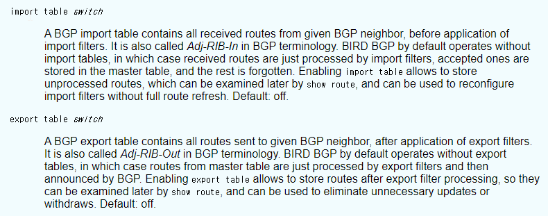
In my senario, I will announce the loopback IP address into the BGP routing protocol. "export" is look like "redestribute" option. In the above there is some important option "import" and "export". In this instruction, there is some explain like below.

I need to install into the BGP routing table which received. I need to edit "import all". Now I can verify the status with "birdc" command.

Host #1

Host #2

root@ip-10-10-0-159:~# birdc

BIRD 1.6.8 ready.

bird> show route

1.1.1.1/32         via 10.10.0.159 on ens5 [static_bgp 12:08:06] * (200)

2.2.2.2/32         via 10.10.0.205 on ens5 [bgp1 12:08:11] * (100) [AS65002i]

1.1.1.2/32         via 10.10.0.159 on ens5 [static_bgp 12:08:06] * (200)

2.2.2.1/32         via 10.10.0.205 on ens5 [bgp1 12:08:11] * (100) [AS65002i]

root@ip-10-10-0-205:~# birdc

BIRD 1.6.8 ready.

bird> show route

2.2.2.2/32         via 10.10.0.205 on ens5 [static_bgp 12:07:51] * (200)

1.1.1.1/32         via 10.10.0.159 on ens5 [bgp1 12:08:11] * (100) [AS65001i]

2.2.2.1/32         via 10.10.0.205 on ens5 [static_bgp 12:07:51] * (200)

1.1.1.2/32         via 10.10.0.159 on ens5 [bgp1 12:08:11] * (100) [AS65001i]

I can see the BGP routing table "1.1.1.1", "1.1.1.2", "2.2.2.1" and "2.2.2.2" are updated. Also I can see the status with "show protocols all" command

bird> show protocols all 

name     proto    table    state  since       info

kernel1  Kernel   master   up     12:08:06    

  Preference:     10

  Input filter:   ACCEPT

  Output filter:  REJECT

  Routes:         0 imported, 0 exported, 0 preferred

  Route change stats:     received   rejected   filtered    ignored   accepted

    Import updates:              0          0          0          0          0

    Import withdraws:            0          0        ---          0          0

    Export updates:              6          0          6        ---          0

    Export withdraws:            0        ---        ---        ---          0

device1  Device   master   up     12:08:06    

  Preference:     240

  Input filter:   ACCEPT

  Output filter:  REJECT

  Routes:         0 imported, 0 exported, 0 preferred

  Route change stats:     received   rejected   filtered    ignored   accepted

    Import updates:              0          0          0          0          0

    Import withdraws:            0          0        ---          0          0

    Export updates:              0          0          0        ---          0

    Export withdraws:            0        ---        ---        ---          0

static_bgp Static   master   up     12:08:06    

  Preference:     200

  Input filter:   ACCEPT

  Output filter:  REJECT

  Routes:         2 imported, 0 exported, 2 preferred

  Route change stats:     received   rejected   filtered    ignored   accepted

    Import updates:              2          0          0          0          2

    Import withdraws:            0          0        ---          0          0

    Export updates:              0          0          0        ---          0

    Export withdraws:            0        ---        ---        ---          0

bgp1     BGP      master   up     12:08:11    Established   

  Preference:     100

  Input filter:   ACCEPT

  Output filter:  (unnamed)

  Routes:         2 imported, 2 exported, 2 preferred

  Route change stats:     received   rejected   filtered    ignored   accepted

    Import updates:              2          0          0          0          2

    Import withdraws:            0          0        ---          0          0

    Export updates:              4          2          0        ---          2

    Export withdraws:            0        ---        ---        ---          0

  BGP state:          Established

    Neighbor address: 10.10.0.205

    Neighbor AS:      65002

    Neighbor ID:      10.10.0.205

    Neighbor caps:    refresh enhanced-refresh restart-aware llgr-aware AS4

    Session:          external AS4

    Source address:   10.10.0.159

    Hold timer:       186/240

    Keepalive timer:  52/80


5. Installing over the Kernal Routing table

Even if bird has the routing table, I can not see the routing table over the system. 

root@ip-10-10-0-159:~# netstat -nr

Kernel IP routing table

Destination     Gateway         Genmask         Flags   MSS Window  irtt Iface

0.0.0.0         10.10.0.1       0.0.0.0         UG        0 0          0 ens5

10.10.0.0       0.0.0.0         255.255.255.0   U         0 0          0 ens5

10.10.0.1       0.0.0.0         255.255.255.255 UH        0 0          0 ens5

Because of this, It is not easy to verify the status if this routing work or not. I need to edit "/etc/bird/bird.conf"

protocol kernel {

        scan time 60;

        import all;

        export all;

}

After then, the routing table will be like below.

Host #1

Host #2

root@ip-10-10-0-159:~# netstat -nr

Kernel IP routing table

Destination     Gateway         Genmask         Flags   MSS Window  irtt Iface

0.0.0.0         10.10.0.1       0.0.0.0         UG        0 0          0 ens5

1.1.1.1         10.10.0.159     255.255.255.255 UGH       0 0          0 ens5

1.1.1.2         10.10.0.159     255.255.255.255 UGH       0 0          0 ens5

2.2.2.1         10.10.0.205     255.255.255.255 UGH       0 0          0 ens5

2.2.2.2         10.10.0.205     255.255.255.255 UGH       0 0          0 ens5

10.10.0.0       0.0.0.0         255.255.255.0   U         0 0          0 ens5

10.10.0.1       0.0.0.0         255.255.255.255 UH        0 0          0 ens5

root@ip-10-10-0-205:~# netstat -nr

Kernel IP routing table

Destination     Gateway         Genmask         Flags   MSS Window  irtt Iface

0.0.0.0         10.10.0.1       0.0.0.0         UG        0 0          0 ens5

1.1.1.1         10.10.0.159     255.255.255.255 UGH       0 0          0 ens5

1.1.1.2         10.10.0.159     255.255.255.255 UGH       0 0          0 ens5

2.2.2.1         10.10.0.205     255.255.255.255 UGH       0 0          0 ens5

2.2.2.2         10.10.0.205     255.255.255.255 UGH       0 0          0 ens5

10.10.0.0       0.0.0.0         255.255.255.0   U         0 0          0 ens5

10.10.0.1       0.0.0.0         255.255.255.255 UH        0 0          0 ens5

I will use the AWS instance. To verify I need to change the option, "source and destination checking option". This option will drop the packet when the source and destination does not match.

And then, I can transfer ICMP packet like below.

Host #1 Host #2

This is the simple BGP routing with Bird. If I have chance to learn more deep-dive. I will handle about it next time. 

Reference 

[ 1 ] https://bird.network.cz/

[ 2 ] https://gitlab.labs.nic.cz/labs/bird

[ 3 ] https://launchpad.net/~cz.nic-labs/+archive/ubuntu/bird

[ 4 ] https://bird.network.cz/pipermail/bird-users/2011-September/002425.html

[ 5 ] https://blog.marquis.co/configuring-bgp-using-bird-on-ubuntu-14-04lts/

[ 6 ] https://skyenet.tech/bird/


Recently, I have some questions about the ECMP load-balancing on CISCO switch. I have already known that the traffic will be distrubute according to each interfaces. However, I can not understand the method for this. This is good chance for me to learn.


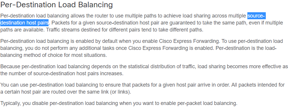
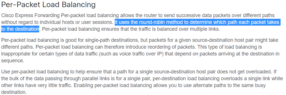
I have read this instruction. I read some terms, "Per Destination" and "Per Packet". In this instruction. It will be more useful to understand.

By this instruction, I can see the configuration paramter on interface like below.

For this verification, I will set up the GNS simulator like below. There are 3 links connected each other.

I will see the wireshark packet over each interface.


1. Per-Destination Algorithm 


"Per-Desination" is default configuration. Therefore, it is now shown when I enter the CLI "ip load-sharing per-destination".

This algorithm is more similar with hashing method. The traffic will transfer over same interface. R1 has 3 loopback IP address, 1.1.1.1, 1.1.1.2 and 1.1.1.3. I will do ICMP with source. The traffic will use different links. However, It will be the same link when the source and destination are same.


[R1# ping 2.2.2.2 source 1.1.1.1 repeat 1]

R1 send ICMP request over Fa 2/1 and received over Fa 2/3.


[R1# ping 2.2.2.2 source 1.1.1.2 repeat 1]

R1 send ICMP request over Fa 2/2 and received over Fa 2/1.


[R1# ping 2.2.2.2 source 1.1.1.3 repeat 1]

R1 send ICMP request over Fa 2/2 and received over Fa 2/1.


Now I will do again in 10 minutes. It will be the same result. 

[R1# ping 2.2.2.2 source 1.1.1.2 repeat 1]

R1 send ICMP request over Fa 2/2 and received over Fa 2/1.


2. Select load-sharing algorithm for "Per-Destination"


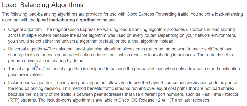
This configuration give some option between R1 and R2. "Per-Destination" is the hashing algorithm. Thus R1 and R2 will show the same result. Because of this, some link can be intensive. For example, R1 --> Link 1 --> R2, R2 --> Link 1 --> R1 can be happend. Thus "Universal algorithm" make more dynmic distrubution on each switch with difference link.


3. Per Packet Algorithm.


I will configure like below on R1 and R2 switch.

After then, I will try to ping to R2. R2 has loopback IP address, 2.2.2.2/32. 

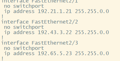
I will get the result like below. This result show that the traffic are distributed by packet, even if it is single connection (source-destination IP address pair)

[FastEthernet 2/1]

[FastEthernet 2/2]

[FastEthernet 2/3]


Reference

[ 1 ] https://networkengineering.stackexchange.com/questions/27914/example-of-ecmp-uses-hashing-technique

[ 2 ] https://www.cisco.com/c/en/us/td/docs/switches/datacenter/sw/4_2/nx-os/unicast/configuration/guide/l3_cli_nxos/l3_manage-routes.html#wp1114960

[ 3 ] https://www.cisco.com/c/en/us/td/docs/ios-xml/ios/ipswitch_cef/configuration/15-mt/isw-cef-15-mt-book/isw-cef-load-balancing.html#GUID-303F07B8-A52B-4BD3-A1F8-54DF24493D8E

How does the OSPF cost work? 


In this post, I will handle the OSPF cost (OSPF cost and auto-cost reference-bandwidth). Normally, I use the OSPF with default setting. 


1. Pre-requisite.


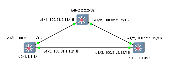
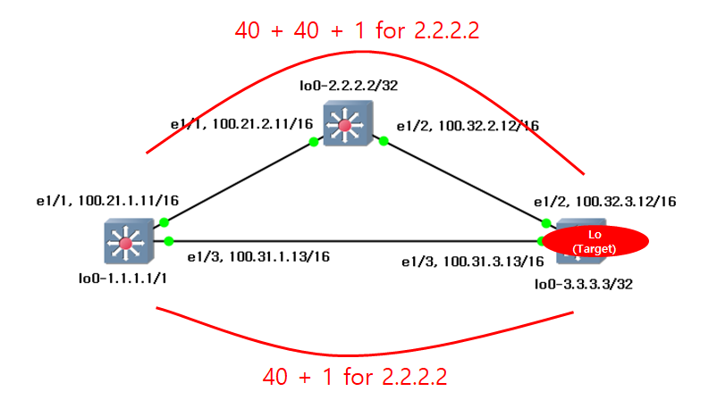
This is my environment to re-produce. I will write the simple configuration with default values.

s1 (1.1.1.1/32)

s2 (2.2.2.2/32)

s3 (3.3.3.3/32)

feature ospf

interface Ethernet1/1

  no switchport

  ip address 100.21.1.11/16

  ip router ospf 1 area 0.0.0.0

  no shutdown


interface Ethernet1/3

  no switchport

  ip address 100.31.1.13/16

  ip router ospf 1 area 0.0.0.0

  no shutdown


interface loopback0

  ip address 1.1.1.1/32

  ip router ospf 1 area 0.0.0.0


router ospf 1

  router-id 1.1.1.1

feature ospf

interface Ethernet1/1

  no switchport

  ip address 100.21.2.11/16

  ip router ospf 2 area 0.0.0.0

  no shutdown


interface Ethernet1/2

  no switchport

  ip address 100.32.2.12/16

  ip router ospf 2 area 0.0.0.0

  no shutdown


interface loopback0

  ip address 2.2.2.2/32

  ip router ospf 2 area 0.0.0.0


router ospf 2

  router-id 2.2.2.2

feature ospf

interface Ethernet1/2

  no switchport

  ip address 100.32.3.12/16

  ip router ospf 3 area 0.0.0.0

  no shutdown


interface Ethernet1/3

  no switchport

  ip address 100.31.3.13/16

  ip router ospf 3 area 0.0.0.0

  no shutdown


interface loopback0

  ip address 3.3.3.3/32

  ip router ospf 3 area 0.0.0.0


router ospf 3

  router-id 3.3.3.3


2. Verify default status.


With default values, I can see the routing table over s1.

s1# show ip route

1.1.1.1/32, ubest/mbest: 2/0, attached

    *via 1.1.1.1, Lo0, [0/0], 00:39:21, local

    *via 1.1.1.1, Lo0, [0/0], 00:39:21, direct

2.2.2.2/32, ubest/mbest: 1/0

    *via 100.21.2.11, Eth1/1, [110/41], 00:35:38, ospf-1, intra

3.3.3.3/32, ubest/mbest: 1/0

    *via 100.31.3.13, Eth1/3, [110/41], 00:33:43, ospf-1, intra

100.21.0.0/16, ubest/mbest: 1/0, attached

    *via 100.21.1.11, Eth1/1, [0/0], 00:36:44, direct

100.21.1.11/32, ubest/mbest: 1/0, attached

    *via 100.21.1.11, Eth1/1, [0/0], 00:36:44, local

100.31.0.0/16, ubest/mbest: 1/0, attached

    *via 100.31.1.13, Eth1/3, [0/0], 00:34:24, direct

100.31.1.13/32, ubest/mbest: 1/0, attached

    *via 100.31.1.13, Eth1/3, [0/0], 00:34:24, local

100.32.0.0/16, ubest/mbest: 2/0

    *via 100.21.2.11, Eth1/1, [110/80], 00:33:43, ospf-1, intra

    *via 100.31.3.13, Eth1/3, [110/80], 00:33:43, ospf-1, intra

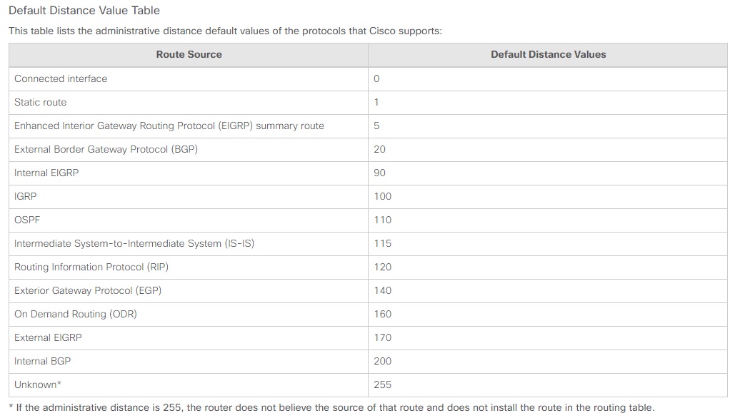
I can see the 2 kinds of values, [110/41] and [110/80]. The first value is the preference which is called as the administrative distance. In this instruction, there is the table list. In my case, I used the OSPF protocol which has 110 value as the default distance values.

The second value is the metric which means the cost. The smaller value for the cost has higher priority

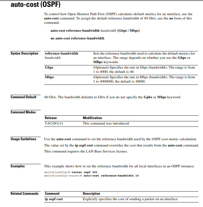
From [110/41] and [110/80], "41" and "80" are the metric cost. Before calcuate these values, I need to understand the "auto-cost referece-bandwidth".


3. About auto-cost referece-bandwidth.


The cost is obtained by "auto-cost reference-bandwidth / interface bandwidth". In this instruction, it show how to configure this auto-cost reference-bandwidth. This is overview.

In my case, I used the Cisco Nexus image. Therefore, the default value is like below from this instruction.

I can verify this value with command, "show ip ospf". This is the sample from s1.

s1# show ip ospf

 Routing Process 1 with ID 1.1.1.1 VRF default

 Routing Process Instance Number 1

 Stateful High Availability enabled

 Graceful-restart is configured

   Grace period: 60 state: Inactive

   Last graceful restart exit status: None

 Supports only single TOS(TOS0) routes

 Supports opaque LSA

 Administrative distance 110

 Reference Bandwidth is 40000 Mbps

 SPF throttling delay time of 200.000 msecs,

   SPF throttling hold time of 1000.000 msecs,

   SPF throttling maximum wait time of 5000.000 msecs

 LSA throttling start time of 0.000 msecs,

   LSA throttling hold interval of 5000.000 msecs,

   LSA throttling maximum wait time of 5000.000 msecs

 Minimum LSA arrival 1000.000 msec

 LSA group pacing timer 10 secs

 Maximum paths to destination 8

 Number of external LSAs 0, checksum sum 0

 Number of opaque AS LSAs 0, checksum sum 0

 Number of areas is 1, 1 normal, 0 stub, 0 nssa

 Number of active areas is 1, 1 normal, 0 stub, 0 nssa

 Install discard route for summarized external routes.

 Install discard route for summarized internal routes.

   Area BACKBONE(0.0.0.0)

        Area has existed for 02:52:56

        Interfaces in this area: 3 Active interfaces: 3

        Passive interfaces: 0  Loopback interfaces: 1

        No authentication available

        SPF calculation has run 9 times

         Last SPF ran for 0.001811s

        Area ranges are

        Number of LSAs: 6, checksum sum 0x30590

Reference Bandwidth is 40000 Mbps. In s1, ethernet 1/1 and ethernet 1/3 have 1Gbps Bandwidth

s1# show inter et 1/1
Ethernet1/1 is up
admin state is up, Dedicated Interface
  Hardware: 100/1000/10000 Ethernet, address: 0cfc.6a48.f207 (bia 0cfc.6a48.f208 )
  Internet Address is 100.21.1.11/16
  MTU 1500 bytes, BW 1000000 Kbit, DLY 10 usec
  reliability 255/255, txload 1/255, rxload 1/255
  Encapsulation ARPA, medium is broadcast
  full-duplex, 1000 Mb/s


s1# show inter et 1/3
Ethernet1/3 is up
admin state is up, Dedicated Interface
  Hardware: 100/1000/10000 Ethernet, address: 0cfc.6a48.f207 (bia 0cfc.6a48.f20a )
  Internet Address is 100.31.1.13/16
  MTU 1500 bytes, BW 1000000 Kbit, DLY 10 usec
  reliability 255/255, txload 1/255, rxload 1/255
  Encapsulation ARPA, medium is broadcast
  full-duplex, 1000 Mb/s

Thus, 40000 Mbps / 1000 Mbps = 40. This is the cost. I can verify the value only with command "show ip ospf interface" also. The below is the sample from s1.

s1# show ip ospf interface

 Ethernet1/1 is up, line protocol is up

    IP address 100.21.1.11/16

    Process ID 1 VRF default, area 0.0.0.0

    Enabled by interface configuration

    State BDR, Network type BROADCAST, cost 40

    Index 2, Transmit delay 1 sec, Router Priority 1

    Designated Router ID: 2.2.2.2, address: 100.21.2.11

    Backup Designated Router ID: 1.1.1.1, address: 100.21.1.11

    1 Neighbors, flooding to 1, adjacent with 1

    Timer intervals: Hello 10, Dead 40, Wait 40, Retransmit 5

      Hello timer due in 00:00:04

    No authentication

    Number of opaque link LSAs: 0, checksum sum 0

 Ethernet1/3 is up, line protocol is up

    IP address 100.31.1.13/16

    Process ID 1 VRF default, area 0.0.0.0

    Enabled by interface configuration

    State BDR, Network type BROADCAST, cost 40

    Index 3, Transmit delay 1 sec, Router Priority 1

    Designated Router ID: 3.3.3.3, address: 100.31.3.13

    Backup Designated Router ID: 1.1.1.1, address: 100.31.1.13

    1 Neighbors, flooding to 1, adjacent with 1

    Timer intervals: Hello 10, Dead 40, Wait 40, Retransmit 5

      Hello timer due in 00:00:03

    No authentication

    Number of opaque link LSAs: 0, checksum sum 0

 loopback0 is up, line protocol is up

    IP address 1.1.1.1/32

    Process ID 1 VRF default, area 0.0.0.0

    Enabled by interface configuration

    State LOOPBACK, Network type LOOPBACK, cost 1

    Index 1


I need to calculate these values. In this instruction, it show how to calculate and select the path.


4. Analysis the OSPF routing cost.


In s1 switch, [110/41] and [110/80] are the values as the cost. 

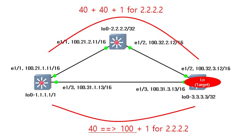
I need to see more detail. "3.3.3.3" is the loopback interface. This IP address can be obtain with 2 path. "81" and "41" are the cost values. "41" is lower values. This is selected.


5. (Option 1) Adjust the Interface Bandwidth to change the path.  


There are many method to determine the path. Most simple way is the change the interface bandwidth and speed. I change the interface bandwidth like below. Please read this instruction.

s1 (1.1.1.1/32)

s3 (3.3.3.3/32)

s1(config)# inter et 1/3

s1(config-if)# bandwidth 100000

s3(config)# inter et 1/3

s3(config-if)# bandwidth 100000

After then, I can check the interface bandwidth status

s1# show ip ospf inter et 1/3
 Ethernet1/3 is up, line protocol is up
    IP address 100.31.1.13/16
    Process ID 1 VRF default, area 0.0.0.0
    Enabled by interface configuration
    State BDR, Network type BROADCAST, cost 400
    Index 3, Transmit delay 1 sec, Router Priority 1
    Designated Router ID: 3.3.3.3, address: 100.31.3.13
    Backup Designated Router ID: 1.1.1.1, address: 100.31.1.13
    1 Neighbors, flooding to 1, adjacent with 1
    Timer intervals: Hello 10, Dead 40, Wait 40, Retransmit 5
      Hello timer due in 00:00:03
    No authentication
    Number of opaque link LSAs: 0, checksum sum 0


s3# show ip ospf interface ethernet 1/3
 Ethernet1/3 is up, line protocol is up
    IP address 100.31.3.13/16
    Process ID 3 VRF default, area 0.0.0.0
    Enabled by interface configuration
    State DR, Network type BROADCAST, cost 400
    Index 3, Transmit delay 1 sec, Router Priority 1
    Designated Router ID: 3.3.3.3, address: 100.31.3.13
    Backup Designated Router ID: 1.1.1.1, address: 100.31.1.13
    1 Neighbors, flooding to 1, adjacent with 1
    Timer intervals: Hello 10, Dead 40, Wait 40, Retransmit 5
      Hello timer due in 00:00:06
    No authentication
    Number of opaque link LSAs: 0, checksum sum 0

Now, I can see the routing table changed like below.

s1# show ip route

1.1.1.1/32, ubest/mbest: 2/0, attached

    *via 1.1.1.1, Lo0, [0/0], 00:07:12, local

    *via 1.1.1.1, Lo0, [0/0], 00:07:12, direct

2.2.2.2/32, ubest/mbest: 1/0

    *via 100.21.2.11, Eth1/1, [110/41], 00:06:11, ospf-1, intra

3.3.3.3/32, ubest/mbest: 1/0

    *via 100.21.2.11, Eth1/1, [110/81], 00:05:29, ospf-1, intra

100.21.0.0/16, ubest/mbest: 1/0, attached

    *via 100.21.1.11, Eth1/1, [0/0], 00:07:13, direct

100.21.1.11/32, ubest/mbest: 1/0, attached

    *via 100.21.1.11, Eth1/1, [0/0], 00:07:13, local

100.31.0.0/16, ubest/mbest: 1/0, attached

    *via 100.31.1.13, Eth1/3, [0/0], 00:07:12, direct

100.31.1.13/32, ubest/mbest: 1/0, attached

    *via 100.31.1.13, Eth1/3, [0/0], 00:07:12, local

100.32.0.0/16, ubest/mbest: 1/0

    *via 100.21.2.11, Eth1/1, [110/80], 00:05:29, ospf-1, intra


6. (Option 2) Adjust the auto-cost reference bandwidth to change the path.


Auto-cost reference-bandwidth is the global parameter. Therefore, I change this value on s1 switch. There is no effect. Also there is no effect even if I change the value on s2 switch.

In this post, I will show how this value is changed.

s1(config)# router ospf 1
s1(config-router)# auto-cost reference-bandwidth 10000
s1(config-router)# exit

I can verify the ospf information 

s1# show ip ospf

 Routing Process 1 with ID 1.1.1.1 VRF default

 Routing Process Instance Number 1

 Stateful High Availability enabled

 Graceful-restart is configured

   Grace period: 60 state: Inactive

   Last graceful restart exit status: None

 Supports only single TOS(TOS0) routes

 Supports opaque LSA

 Administrative distance 110

 Reference Bandwidth is 10000 Mbps

Therefore, the routing table will be changed like below.

s1# show ip route

1.1.1.1/32, ubest/mbest: 2/0, attached

    *via 1.1.1.1, Lo0, [0/0], 00:18:15, local

    *via 1.1.1.1, Lo0, [0/0], 00:18:15, direct

2.2.2.2/32, ubest/mbest: 1/0

    *via 100.21.2.11, Eth1/1, [110/11], 00:02:25, ospf-1, intra

3.3.3.3/32, ubest/mbest: 1/0

    *via 100.31.3.13, Eth1/3, [110/11], 00:02:25, ospf-1, intra

100.21.0.0/16, ubest/mbest: 1/0, attached

    *via 100.21.1.11, Eth1/1, [0/0], 00:18:16, direct

100.21.1.11/32, ubest/mbest: 1/0, attached

    *via 100.21.1.11, Eth1/1, [0/0], 00:18:16, local

100.31.0.0/16, ubest/mbest: 1/0, attached

    *via 100.31.1.13, Eth1/3, [0/0], 00:18:15, direct

100.31.1.13/32, ubest/mbest: 1/0, attached

    *via 100.31.1.13, Eth1/3, [0/0], 00:18:15, local

100.32.0.0/16, ubest/mbest: 2/0

    *via 100.21.2.11, Eth1/1, [110/50], 00:02:25, ospf-1, intra

    *via 100.31.3.13, Eth1/3, [110/50], 00:02:25, ospf-1, intra


7. (Option 3) Adjust the ip ospf cost to change the path.


This is more effective way. However, I do not recommand this way. Because this can make complexity. In this instruction, it show how to configure. This configuration will be done on each interface.

s1(config)# inter ethernet 1/3
s1(config-if)# ip ospf cost 100
s1(config-if)# exit


This is the result on s1 switch

s1# show ip ospf interface ethernet 1/3

 Ethernet1/3 is up, line protocol is up

    IP address 100.31.1.13/16

    Process ID 1 VRF default, area 0.0.0.0

    Enabled by interface configuration

    State BDR, Network type BROADCAST, cost 100

    Index 3, Transmit delay 1 sec, Router Priority 1

    Designated Router ID: 3.3.3.3, address: 100.31.3.13

    Backup Designated Router ID: 1.1.1.1, address: 100.31.1.13

    1 Neighbors, flooding to 1, adjacent with 1

    Timer intervals: Hello 10, Dead 40, Wait 40, Retransmit 5

      Hello timer due in 00:00:03

    No authentication

    Number of opaque link LSAs: 0, checksum sum 0

Now, the path will be adjusted like below.

The routing table for s1 will be changed like below.

s1# show ip route

1.1.1.1/32, ubest/mbest: 2/0, attached

    *via 1.1.1.1, Lo0, [0/0], 00:24:35, local

    *via 1.1.1.1, Lo0, [0/0], 00:24:35, direct

2.2.2.2/32, ubest/mbest: 1/0

    *via 100.21.2.11, Eth1/1, [110/41], 00:04:23, ospf-1, intra

3.3.3.3/32, ubest/mbest: 1/0

    *via 100.21.2.11, Eth1/1, [110/81], 00:01:52, ospf-1, intra

100.21.0.0/16, ubest/mbest: 1/0, attached

    *via 100.21.1.11, Eth1/1, [0/0], 00:24:36, direct

100.21.1.11/32, ubest/mbest: 1/0, attached

    *via 100.21.1.11, Eth1/1, [0/0], 00:24:36, local

100.31.0.0/16, ubest/mbest: 1/0, attached

    *via 100.31.1.13, Eth1/3, [0/0], 00:24:35, direct

100.31.1.13/32, ubest/mbest: 1/0, attached

    *via 100.31.1.13, Eth1/3, [0/0], 00:24:35, local

100.32.0.0/16, ubest/mbest: 1/0

    *via 100.21.2.11, Eth1/1, [110/80], 00:01:52, ospf-1, intra

This is the OSPF cost concept.


Reference


[ 1 ] https://www.cisco.com/c/en/us/support/docs/ip/border-gateway-protocol-bgp/15986-admin-distance.html

[ 2 ] http://www.informit.com/articles/article.aspx?p=26129&seqNum=7

[ 3 ] https://www.computernetworkingnotes.com/ccna-study-guide/ospf-metric-cost-calculation-formula-explained.html

[ 4 ] https://www.cisco.com/c/en/us/td/docs/switches/datacenter/nexus5500/sw/command/reference/unicast/n5500-ucast-cr/n5k-ospf_cmds_a.pdf

[ 5 ] https://www.ciscolive.com/c/dam/r/ciscolive/us/docs/2012/pdf/BRKARC-3472.pdf

[ 6 ] https://www.cisco.com/c/en/us/td/docs/switches/datacenter/sw/5_x/nx-os/interfaces/configuration/guide/if_cli/if_layer3int.html

[ 7 ] https://community.cisco.com/t5/networking-documents/how-to-configure-ospf-cost/ta-p/3133153

How to work BGP synchronize and next hop self with Nexus?


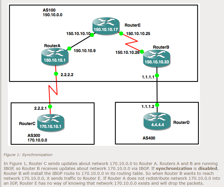
I have already written about BGP concept simply in this another blog in Korean. For the BGP synchronization, I have also written in this blog in Korean. For Next hop self concept, this blog will be helpful. Please do not worry even if you can not read Korean. In this post, I will reproduce this synchorization and next-hop-self with nexus switches.


1. Pre-requisite


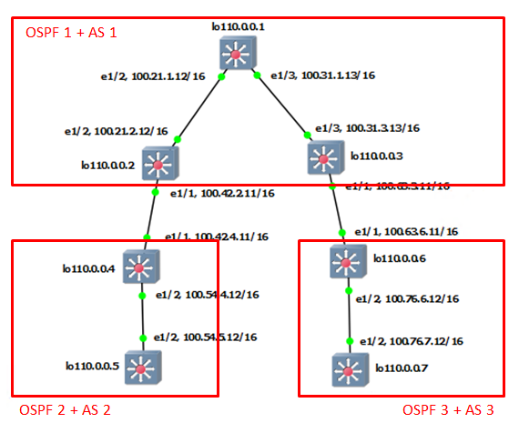
This is my environment for this post. I will configure step by step with below. For "OSPF1 + AS1" part

s1 (lo1 110.0.0.1)

s2 (lo1 110.0.0.2)

s3 (lo1 110.0.0.3)

feature ospf

feature bgp

interface Ethernet1/2

  no switchport

  ip address 100.21.1.12/16

  ip router ospf 1 area 0.0.0.1

  no shutdown

interface Ethernet1/3

  no switchport

  ip address 100.31.1.13/16

  ip router ospf 1 area 0.0.0.1

  no shutdown

interface loopback0

  ip address 110.0.0.1/32

  ip router ospf 1 area 0.0.0.1

router ospf 1

  router-id 110.0.0.1

feature ospf

feature bgp

interface Ethernet1/1

  no switchport

  ip address 100.42.2.11/16

  no shutdown

interface Ethernet1/2

  no switchport

  ip address 100.21.2.12/16

  ip router ospf 1 area 0.0.0.1

  no shutdown

interface loopback0

  ip address 110.0.0.2/32

  ip router ospf 1 area 0.0.0.1

router ospf 1

  router-id 110.0.0.2

router bgp 1

  router-id 110.0.0.2

  log-neighbor-changes

  address-family ipv4 unicast

    network 110.0.0.2/32

  neighbor 100.42.4.11

    remote-as 2

    log-neighbor-changes

    update-source loopback0

    address-family ipv4 unicast

  neighbor 110.0.0.3

    remote-as 1

    update-source loopback0

    address-family ipv4 unicast

feature ospf

feature bgp

interface Ethernet1/1

  no switchport

  ip address 100.63.3.11/16

  no shutdown

interface Ethernet1/3

  no switchport

  ip address 100.31.3.13/16

  ip router ospf 1 area 0.0.0.1

  no shutdown

interface loopback0

  ip address 110.0.0.3/32

  ip router ospf 1 area 0.0.0.1

router ospf 1

  router-id 110.0.0.3

router bgp 1

  router-id 110.0.0.3

  address-family ipv4 unicast

    network 110.0.0.3/32

  neighbor 100.63.6.11

    remote-as 3

    update-source loopback0

    address-family ipv4 unicast

  neighbor 110.0.0.2

    remote-as 1

    update-source loopback0

    address-family ipv4 unicast

For "OSPF2 + AS2" part

s4 (lo1 110.0.0.4)

s5 (lo1 110.0.0.5)

feature ospf

feature bgp

interface Ethernet1/1

  no switchport

  ip address 100.42.4.11/16

  no shutdown

interface Ethernet1/2

  no switchport

  ip address 100.54.4.12/16

  ip router ospf 2 area 0.0.0.2

  no shutdown

interface loopback0

  ip address 110.0.0.4/32

router ospf 2

  router-id 110.0.0.4

router bgp 2

  router-id 110.0.0.4

  log-neighbor-changes

  address-family ipv4 unicast

    network 110.0.0.4/32

  neighbor 100.42.2.11

    remote-as 1

    log-neighbor-changes

    address-family ipv4 unicast

  neighbor 110.42.2.11

    address-family ipv4 unicast

feature ospf

feature bgp

interface Ethernet1/2

  no switchport

  ip address 100.54.5.12/16

  ip router ospf 2 area 0.0.0.2

  no shutdown

interface loopback0

  ip address 110.0.0.5/32

  ip router ospf 2 area 0.0.0.2

router ospf 2

  router-id 110.0.0.5

For "OSPF3 + AS3" part

s6 (lo1 110.0.0.6)

s7 (lo1 110.0.0.7)

feature ospf

feature bgp

interface Ethernet1/1

  no switchport

  ip address 100.63.6.11/16

  no shutdown

interface Ethernet1/2

  no switchport

  ip address 100.76.6.12/16

  ip router ospf 3 area 0.0.0.3

  no shutdown

interface loopback0

  ip address 110.0.0.6/32

router ospf 3

  router-id 110.0.0.6

router bgp 3

  router-id 110.0.0.6

  log-neighbor-changes

  address-family ipv4 unicast

    network 110.0.0.6/32

  neighbor 100.63.3.11

    remote-as 1

    address-family ipv4 unicast

feature ospf

feature bgp

interface Ethernet1/2

  no switchport

  ip address 100.76.7.12/16

  ip router ospf 3 area 0.0.0.3

  no shutdown

interface loopback0

  ip address 110.0.0.7/32

  ip router ospf 3 area 0.0.0.3

router ospf 3

  router-id 110.0.0.7

This is simple configuration. At this time, it is not perfect in traffic flow. In some case, it can not send each other. For example, S4 (110.0.0.4) and S6 (110.0.0.6) can not transfer the packets each other.


2. About BGP synchroization.


To verify the BGP synchronization, I have to look the BGP table on S3 switch.

s3# show ip bgp

BGP routing table information for VRF default, address family IPv4 Unicast

BGP table version is 16, Local Router ID is 110.0.0.3

Status: s-suppressed, x-deleted, S-stale, d-dampened, h-history, *-valid, >-best

Path type: i-internal, e-external, c-confed, l-local, a-aggregate, r-redist, I-i

njected

Origin codes: i - IGP, e - EGP, ? - incomplete, | - multipath, & - backup, 2 - b

est2

   Network            Next Hop            Metric     LocPrf     Weight Path

*>i110.0.0.2/32       110.0.0.2                         100          0 i

*>l110.0.0.3/32       0.0.0.0                           100      32768 i

  i110.0.0.4/32       100.42.4.11                       100          0 2 i

*>e110.0.0.6/32       100.63.6.11                                    0 3 i

This is so strange. Because I did not "no synchorization" in BGP configuration, "110.0.0.4" should not be displayed. In this blog, the concept of the synchronization will be explained.

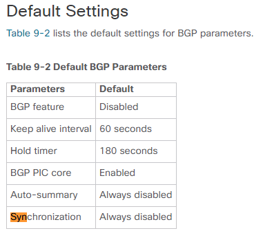
I used nexus switch image for this generation. In this instruction, there are default settings. By these values, the BGP table on S3 switch displayed S4 information.


3. About Next-Hop-Self.


This is not vaild status, even if the BGP table show S4 information. It looks like normal. 

s3# show ip bgp

BGP routing table information for VRF default, address family IPv4 Unicast

BGP table version is 16, Local Router ID is 110.0.0.3

Status: s-suppressed, x-deleted, S-stale, d-dampened, h-history, *-valid, >-best

Path type: i-internal, e-external, c-confed, l-local, a-aggregate, r-redist, I-i

njected

Origin codes: i - IGP, e - EGP, ? - incomplete, | - multipath, & - backup, 2 - b

est2

   Network            Next Hop            Metric     LocPrf     Weight Path

*>i110.0.0.2/32       110.0.0.2                         100          0 i

*>l110.0.0.3/32       0.0.0.0                           100      32768 i

  i110.0.0.4/32       100.42.4.11                       100          0 2 i

*>e110.0.0.6/32       100.63.6.11                                    0 3 i

I need to check the "Next Hop" status. "100.42.4.11" is the IP address between S2 and S4. In the routing table on S3, there is no information.

s3# show ip route

IP Route Table for VRF "default"

'*' denotes best ucast next-hop

'**' denotes best mcast next-hop

'[x/y]' denotes [preference/metric]

'%' in via output denotes VRF 

100.21.0.0/16, ubest/mbest: 1/0

    *via 100.31.1.13, Eth1/3, [110/80], 1d03h, ospf-1, intra

100.31.0.0/16, ubest/mbest: 1/0, attached

    *via 100.31.3.13, Eth1/3, [0/0], 1d04h, direct

100.31.3.13/32, ubest/mbest: 1/0, attached

    *via 100.31.3.13, Eth1/3, [0/0], 1d04h, local

100.63.0.0/16, ubest/mbest: 1/0, attached

    *via 100.63.3.11, Eth1/1, [0/0], 1d04h, direct

100.63.3.11/32, ubest/mbest: 1/0, attached

    *via 100.63.3.11, Eth1/1, [0/0], 1d04h, local

110.0.0.1/32, ubest/mbest: 1/0

    *via 100.31.1.13, Eth1/3, [110/41], 1d03h, ospf-1, intra

110.0.0.2/32, ubest/mbest: 1/0

    *via 100.31.1.13, Eth1/3, [110/81], 1d03h, ospf-1, intra

110.0.0.3/32, ubest/mbest: 2/0, attached

    *via 110.0.0.3, Lo0, [0/0], 1d04h, local

    *via 110.0.0.3, Lo0, [0/0], 1d04h, direct

110.0.0.6/32, ubest/mbest: 1/0

    *via 100.63.6.11, [20/0], 1d02h, bgp-1, external, tag 3

It is not valid because the nexthop is not valid. To resolve this, there is the 2 ways. First, add the static route. Second, Next-hop-self.

# Add static route on s3

s3(config)# ip route 100.42.0.0/16 110.0.0.1

And then, I can see the BGP table. The status should be changed by valid.

s3# show ip bgp

BGP routing table information for VRF default, address family IPv4 Unicast

BGP table version is 17, Local Router ID is 110.0.0.3

Status: s-suppressed, x-deleted, S-stale, d-dampened, h-history, *-valid, >-best

Path type: i-internal, e-external, c-confed, l-local, a-aggregate, r-redist, I-i

njected

Origin codes: i - IGP, e - EGP, ? - incomplete, | - multipath, & - backup, 2 - b

est2

   Network            Next Hop            Metric     LocPrf     Weight Path

*>i110.0.0.2/32       110.0.0.2                         100          0 i

*>l110.0.0.3/32       0.0.0.0                           100      32768 i

*>i110.0.0.4/32       100.42.4.11                       100          0 2 i

*>e110.0.0.6/32       100.63.6.11                                    0 3 i

Now, I will configure "next-hop-self" on s2 switch after remove static route on s3 switch.

# Remove static route on s3

s3(config)# no ip route 100.42.0.0/16 110.0.0.1 


# Add next hop self configuratoin on s2

s2(config)# router bgp 1
s2(config-router)# neighbor 110.0.0.3
s2(config-router-neighbor)# address-family ipv4 unicast
s2(config-router-neighbor-af)# next-hop-self
s2(config-router-neighbor-af)# end

Now look at the s3 switch with "show ip bgp" command

s3# show ip bgp

BGP routing table information for VRF default, address family IPv4 Unicast

BGP table version is 19, Local Router ID is 110.0.0.3

Status: s-suppressed, x-deleted, S-stale, d-dampened, h-history, *-valid, >-best

Path type: i-internal, e-external, c-confed, l-local, a-aggregate, r-redist, I-i

njected

Origin codes: i - IGP, e - EGP, ? - incomplete, | - multipath, & - backup, 2 - b

est2

   Network            Next Hop            Metric     LocPrf     Weight Path

*>i110.0.0.2/32       110.0.0.2                         100          0 i

*>l110.0.0.3/32       0.0.0.0                           100      32768 i

*>i110.0.0.4/32       110.0.0.2                         100          0 2 i

*>e110.0.0.6/32       100.63.6.11                                    0 3 i

There are 2 change. First, the status is changed as the valid. Second the next hop ip address is changed from "100.42.4.11" to "110.0.0.2". This "next-hop-self" feature make the "ebgp" existance clear. Now I will do again in s3 switch for next step.

s3(config)# router bgp 1

s3(config-router)# nei 110.0.0.2

s3(config-router-neighbor)# address-family ipv4 unicast

s3(config-router-neighbor-af)# next-hop-self

s3(config-router-neighbor-af)# exit


4. Troubleshooting.


Look at routing table and bgp table on the s4 switch and s6 switch. From s4 switch,

s4# show ip route

IP Route Table for VRF "default"

'*' denotes best ucast next-hop

'**' denotes best mcast next-hop

'[x/y]' denotes [preference/metric]

'%' in via output denotes VRF 

100.42.0.0/16, ubest/mbest: 1/0, attached

    *via 100.42.4.11, Eth1/1, [0/0], 1d04h, direct

100.42.4.11/32, ubest/mbest: 1/0, attached

    *via 100.42.4.11, Eth1/1, [0/0], 1d04h, local

100.54.0.0/16, ubest/mbest: 1/0, attached

    *via 100.54.4.12, Eth1/2, [0/0], 1d04h, direct

100.54.4.12/32, ubest/mbest: 1/0, attached

    *via 100.54.4.12, Eth1/2, [0/0], 1d04h, local

110.0.0.2/32, ubest/mbest: 1/0

    *via 100.42.2.11, [20/0], 1d02h, bgp-2, external, tag 1

110.0.0.3/32, ubest/mbest: 1/0

    *via 100.42.2.11, [20/0], 1d02h, bgp-2, external, tag 1

110.0.0.4/32, ubest/mbest: 2/0, attached

    *via 110.0.0.4, Lo0, [0/0], 1d04h, local

    *via 110.0.0.4, Lo0, [0/0], 1d04h, direct

110.0.0.5/32, ubest/mbest: 1/0

    *via 100.54.5.12, Eth1/2, [110/41], 00:40:49, ospf-2, intra

110.0.0.6/32, ubest/mbest: 1/0

    *via 100.42.2.11, [20/0], 00:03:43, bgp-2, external, tag 1

s4# show ip bgp

BGP routing table information for VRF default, address family IPv4 Unicast

BGP table version is 12, Local Router ID is 110.0.0.4

Status: s-suppressed, x-deleted, S-stale, d-dampened, h-history, *-valid, >-best

Path type: i-internal, e-external, c-confed, l-local, a-aggregate, r-redist, I-i

njected

Origin codes: i - IGP, e - EGP, ? - incomplete, | - multipath, & - backup, 2 - b

est2

   Network            Next Hop            Metric     LocPrf     Weight Path

*>e110.0.0.2/32       100.42.2.11                                    0 1 i

*>e110.0.0.3/32       100.42.2.11                                    0 1 i

*>l110.0.0.4/32       0.0.0.0                           100      32768 i

*>e110.0.0.6/32       100.42.2.11                                    0 1 3 i

From s6 switch,

s6# show ip route

IP Route Table for VRF "default"

'*' denotes best ucast next-hop

'**' denotes best mcast next-hop

'[x/y]' denotes [preference/metric]

'%' in via output denotes VRF 

100.63.0.0/16, ubest/mbest: 1/0, attached

    *via 100.63.6.11, Eth1/1, [0/0], 1d04h, direct

100.63.6.11/32, ubest/mbest: 1/0, attached

    *via 100.63.6.11, Eth1/1, [0/0], 1d04h, local

100.76.0.0/16, ubest/mbest: 1/0, attached

    *via 100.76.6.12, Eth1/2, [0/0], 1d04h, direct

100.76.6.12/32, ubest/mbest: 1/0, attached

    *via 100.76.6.12, Eth1/2, [0/0], 1d04h, local

110.0.0.2/32, ubest/mbest: 1/0

    *via 100.63.3.11, [20/0], 1d02h, bgp-3, external, tag 1

110.0.0.3/32, ubest/mbest: 1/0

    *via 100.63.3.11, [20/0], 1d02h, bgp-3, external, tag 1

110.0.0.4/32, ubest/mbest: 1/0

    *via 100.63.3.11, [20/0], 00:10:28, bgp-3, external, tag 1

110.0.0.6/32, ubest/mbest: 2/0, attached

    *via 110.0.0.6, Lo0, [0/0], 1d04h, local

    *via 110.0.0.6, Lo0, [0/0], 1d04h, direct

110.0.0.7/32, ubest/mbest: 1/0

    *via 100.76.7.12, Eth1/2, [110/41], 00:44:12, ospf-3, intra

s6# show ip bgp

BGP routing table information for VRF default, address family IPv4 Unicast

BGP table version is 15, Local Router ID is 110.0.0.6

Status: s-suppressed, x-deleted, S-stale, d-dampened, h-history, *-valid, >-best

Path type: i-internal, e-external, c-confed, l-local, a-aggregate, r-redist, I-i

njected

Origin codes: i - IGP, e - EGP, ? - incomplete, | - multipath, & - backup, 2 - b

est2

   Network            Next Hop            Metric     LocPrf     Weight Path

*>e110.0.0.2/32       100.63.3.11                                    0 1 i

*>e110.0.0.3/32       100.63.3.11                                    0 1 i

*>e110.0.0.4/32       100.63.3.11                                    0 1 2 i

*>l110.0.0.6/32       0.0.0.0                           100      32768 i

By these informations, I may send traffic each other. However, I can not. Please look at the below, I send the traffic from s4 to s6.

s4# ping 110.0.0.6 source-interface loopback 0

PING 110.0.0.6 (110.0.0.6): 56 data bytes

Request 0 timed out


--- 110.0.0.6 ping statistics ---

2 packets transmitted, 0 packets received, 100.00% packet loss

I have to check the routing table s2 and s3 also. They have also information.

s2# show ip route
110.0.0.4/32, ubest/mbest: 1/0
    *via 100.42.4.11, [20/0], 1d03h, bgp-1, external, tag 2
110.0.0.6/32, ubest/mbest: 1/0
    *via 110.0.0.3, [200/0], 00:09:44, bgp-1, internal, tag 3

s3# show ip route
110.0.0.4/32, ubest/mbest: 1/0
    *via 110.0.0.2, [200/0], 00:14:14, bgp-1, internal, tag 2
110.0.0.6/32, ubest/mbest: 1/0
    *via 100.63.6.11, [20/0], 1d02h, bgp-1, external, tag 3

Now, only s1 switch has been left. In s1 switch, I did not configure for BGP. Because of this, s1 can not get any information for s4 and s6. Now I will add static route simply on s1 switch.

s1(config)# ip route 110.0.0.4/32 110.0.0.2

s1(config)# ip route 110.0.0.5/32 110.0.0.2

s1(config)# ip route 110.0.0.6/32 110.0.0.3

s1(config)# ip route 110.0.0.7/32 110.0.0.3

After this configuration add, I can send the traffic

s4# ping 110.0.0.6 source-interface loopback 0

PING 110.0.0.6 (110.0.0.6): 56 data bytes

64 bytes from 110.0.0.6: icmp_seq=0 ttl=251 time=20.858 ms

64 bytes from 110.0.0.6: icmp_seq=1 ttl=251 time=12.801 ms

64 bytes from 110.0.0.6: icmp_seq=2 ttl=251 time=25.59 ms

64 bytes from 110.0.0.6: icmp_seq=3 ttl=251 time=13.339 ms

64 bytes from 110.0.0.6: icmp_seq=4 ttl=251 time=12.694 ms

--- 110.0.0.6 ping statistics ---

5 packets transmitted, 5 packets received, 0.00% packet loss

round-trip min/avg/max = 12.694/17.056/25.59 ms


Reference


[ 1 ] https://blog.naver.com/happy_jhyo/70151060540

[ 2 ] https://blog.naver.com/happy_jhyo/221284566856

[ 3 ] http://www.nnk.com.au/index.php?option=com_content&view=article&id=22:bgp-synchronization&catid=3:articles&Itemid=5

[ 4 ] https://www.cisco.com/c/en/us/td/docs/switches/datacenter/nexus9000/sw/6-x/unicast/configuration/guide/l3_cli_nxos/l3_bgp.html


What is basic BGP community concept?


This instruction is good reference. In fact, I will analysis this instruction. BGP community is used for filtering and tagging information over routing information. Therefore, routing table information will be controlled by these condistions. Thus I can select the routing information to advertise or update in the table.


1. Pre-requiste (Basic BGP configuration)

This is my environment for this post. 

S1 S2 S3 S4

interface Ethernet1/1 

  no switchport 

  ip address 100.12.1.11/16 

  no shutdown 

interface loopback0 

  ip address 1.1.1.1/32 

interface loopback1 

  ip address 11.11.11.11/32 

!  

router bgp 1 

  router-id 1.1.1.1 

  log-neighbor-changes 

  address-family ipv4 unicast 

    network 1.1.1.1/32 

    network 11.11.11.11/32 

  neighbor 100.12.2.11 

    remote-as 2 

    update-source Ethernet1/1 

    address-family ipv4 unicast

interface Ethernet1/1

  no switchport

  ip address 100.12.2.11/16

  no shutdown

interface Ethernet1/2

  no switchport

  ip address 100.23.2.12/16

  no shutdown

!

interface loopback0

  ip address 2.2.2.2/32

!

interface loopback1

  ip address 22.22.22.22/32

!  

router bgp 2

  router-id 2.2.2.2

  log-neighbor-changes

  address-family ipv4 unicast

    network 2.2.2.2/32

    network 22.22.22.22/32

  neighbor 100.12.1.11

    remote-as 1

    update-source Ethernet1/1

    address-family ipv4 unicast

  neighbor 100.23.3.12

    remote-as 3

    update-source Ethernet1/2

    address-family ipv4 unicast

interface Ethernet1/2

  no switchport

  ip address 100.23.3.12/16

  no shutdown

interface Ethernet1/3

  no switchport

  ip address 100.34.3.13/16

  no shutdown

!

interface loopback0

  ip address 3.3.3.3/32

!

interface loopback1

  ip address 33.33.33.33/32

!

router bgp 3

  router-id 3.3.3.3

  log-neighbor-changes

  address-family ipv4 unicast

    network 3.3.3.3/32

    network 33.33.33.33/32

  neighbor 100.23.2.12

    remote-as 2

    update-source Ethernet1/2

    address-family ipv4 unicast

  neighbor 100.34.4.13

    remote-as 4

    update-source Ethernet1/3

    address-family ipv4 unicast

interface Ethernet1/3

  no switchport

  ip address 100.34.4.13/16

  no shutdown

!

interface loopback0

  ip address 4.4.4.4/32

!

interface loopback1

  ip address 44.44.44.44/32

!

router bgp 4

  router-id 4.4.4.4

  log-neighbor-changes

  address-family ipv4 unicast

    network 4.4.4.4/32

    network 44.44.44.44/32

  neighbor 100.34.3.13

    remote-as 3

    update-source Ethernet1/3

    address-family ipv4 unicast

For nexus, "address-family ipv4 unicast" in neighbor parameter and "address-familiy ipv4 unicast" in global parameter are necessary to advertise to the peer. After configure these, I can verify the routing table and BGP information. From S2

From S3,

From S4

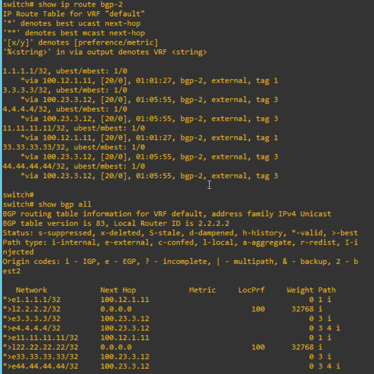
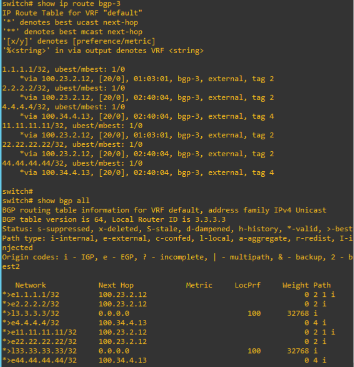
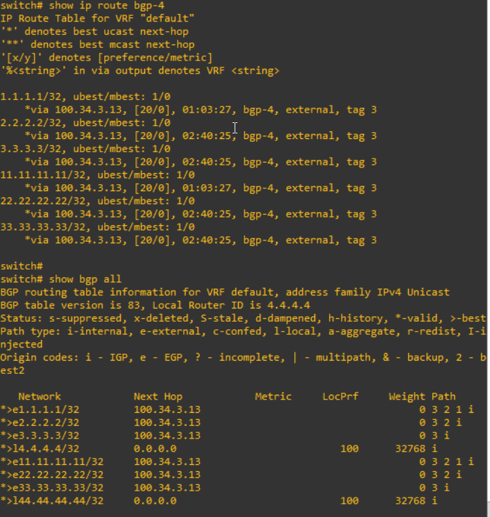
I can confirm that the information from S1 such as "1.1.1.1" and "11.11.11.11" are advertised to S2, S3 and S4.


2. Configure send community


To use the BGP community, I have to configure "send community". There are 2 types, standard and extended. In this struction, the extended community has more information such as VPN services.

I will added the configuration like below.

S1 S2 S3 S4

router bgp 1

  neighbor 100.12.2.11

    address-family ipv4 unicast

      send-community both

router bgp 2

  neighbor 100.12.1.11

    address-family ipv4 unicast

send-community both

  neighbor 100.23.3.12

    address-family ipv4 unicast

send-community both

router bgp 3

  neighbor 100.23.2.12

    address-family ipv4 unicast

send-community both

  neighbor 100.34.4.13

    address-family ipv4 unicast

send-community both

router bgp 4

  neighbor 100.34.3.13

    address-family ipv4 unicast

send-community both 

Please note that there are any differences of routing table after these configuration above.


3. Configure Route-map in and out


To use the BGP community, the route-map is necessary. This route-map affect the routing table. In S3, I will add "route-map" configuration.

!

router bgp 1

neighbor 100.12.2.11

address-family ipv4 unicast

route-map to-remote-as2 out

end

!

"route-map to-remote-as2 out" mean that routing information to transfer out will be controlled with this route-map. Therefore, after this configuration, the routing table will be changed. "1.1.1.1" and  "11.11.11.11" are removed

Now, I will add the policy to set community.

ip prefix-list ip-prefix-1 seq 10 permit 1.1.1.1/32
ip prefix-list ip-prefix-2 seq 10 permit 11.11.11.11/32
route-map to-remote-as2 permit 10
  match ip address prefix-list ip-prefix-1
  set community 12:130
route-map to-remote-as2 permit 20
  match ip address prefix-list ip-prefix-2
  set community 12:150

I check the routing table from S4. "1.1.1.1" and "11.11.11.11" will be updated. 

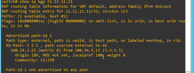
And I can see more detail. I can see the community values are changed on each.

So far, I learn how to set the community with BGP. From now, I will handle how to get the community and use this. This is so similar with above. I will add configure into the S2.

!

router bgp 2

neighbor 100.12.1.11

address-family ipv4 unicast

route-map from-remote-as1 in

end

!

After configure this, the routing table will be changed. "1.1.1.1" and "11.11.11.11" are removed again.

Now, I will add some configuration to get community and use it in S2

ip community-list expanded community-1 seq 1 permit "12:130"

ip community-list expanded community-2 seq 1 permit "12:150"

route-map from-remote-as1 permit 10

  match community community-1

  set local-preference 130

route-map from-remote-as1 permit 20

  match community community-2

  set local-preference 150

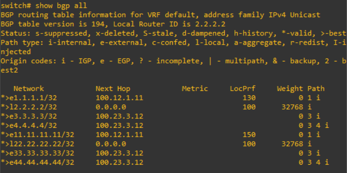
These configuration effect S2 routing table like below.

However, it does not effect S3 and S4, even if the community value is left.


Reference


[ 1 ] https://www.cisco.com/c/en/us/support/docs/ip/border-gateway-protocol-bgp/28784-bgp-community.html

[ 2 ] http://www.ciscopress.com/articles/article.asp?p=2756480&seqNum=12

[ 3 ] https://blog.naver.com/happy_jhyo/221291791846

+ Recent posts