How does the multicast (PIM sparse mode) work with MSDP?
In this post, I will generate the multicast environment with Nx9000v on GNS3. I will handle the multicast with PIM sparse mode.
1. Pre-requiste for Test environments
I will produce this environment to generate the multicast.
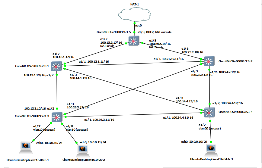
Before I make Multicast environment, I need to prepare NAT for outbound traffic and Multicast test scripts. This is the sample configuration for NAT outbound traffic.
|
conf t feature dhcp feature nat ! ip nat translation max-entries 1023 ! no ip dhcp relay no ipv6 dhcp relay ! inter eth 1/9 no sw ip add dhcp ip nat out no shut exit inter et 1/7 no sw ip add 100.15.5.17/16 ip nat ins no shut exit inter et 1/8 no sw ip add 100.25.5.18/16 ip nat ins no shut exit ! ip acc 1 10 per ip any any exit ! ip nat inside source list 1 interface et1/9 overload ip route 10.0.0.0/24 100.15.1.17 ip route 10.0.0.0/24 100.25.2.18 ip route 20.0.0.0/24 100.15.1.17 ip route 20.0.0.0/24 100.25.2.18 ip route 100.0.0.0/8 100.15.1.17 ip route 100.0.0.0/8 100.25.2.18 ip route 1.1.1.1/32 100.15.1.17 ip route 1.1.1.1/32 100.25.2.18 ip route 2.2.2.2/32 100.15.1.17 ip route 2.2.2.2/32 100.25.2.18 ip route 3.3.3.3/32 100.15.1.17 ip route 3.3.3.3/32 100.25.2.18 ip route 4.4.4.4/32 100.15.1.17 ip route 4.4.4.4/32 100.25.2.18 end ! |
Also I attach the multicast example below
2. Configuration for default environment.
2-1. Configure Core swtich/router
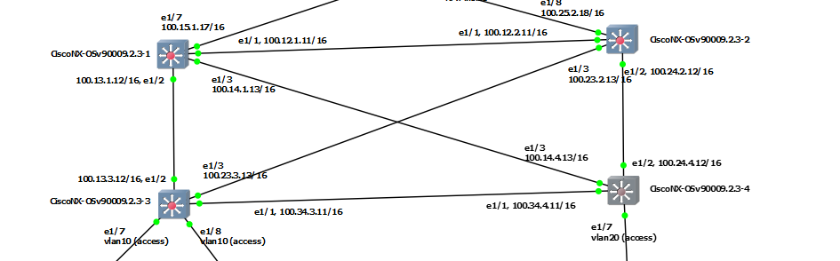
I will make full-mesh connectivity. There are four switch/router. I will name as s1, s2, s3 and s4. On those switch/router, I will run OSPF routing to announce loopback addresses for Router ID and RP point.
|
s1 |
s2 |
s3 |
s4 |
|
conf t |
conf t |
conf t ---------------------------------- |
conf t ---------------------------------- |
In s1 and s2, there are 2 kinds of loopback addresses. One is for the switch/router ID, the other is for the RP address. For loopback address for RP, I will utilize "ghost loopback address" method. Please look at the loopback interface 1 in s1 and s2.
| s1 | s2 |
|
conf t |
conf t |
S1 is the main RP server in normal status. However, it will be changed to s2 when S1 is failed without IP address change. Because of this, I need MSDP (Multicast Source Discovery Protocol). I will handle in later. To announce the network with subnet of loopback interface into OSPF, "Point to Point" is necesary. Now I can see the routing table on S3 and S4 switch/router.
| s3# show ip route ospf-1 | s4# show ip route ospf-1 |
|
1.1.1.1/32, ubest/mbest: 1/0 |
1.1.1.1/32, ubest/mbest: 1/0 |
In red text above, "100.100.100.100" is the RP address for multicast. At this time, the destination should be s1. It will be changed to s2 by "100.100.100.0/24", when s1 is failed.
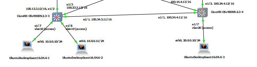
2-2. Configure the Host (PC, Labtop) network.
s3 and s4 is the gateway for each host network. In my scenario, I will use "10.0.0.0/24" for PC1 and "20.0.0.0/24" for PC2.
I have already done for the gateway above.
|
S3 |
S4 |
|
! conf t ! inter vlan 10 ip router ospf 1 area 0.0.0.0 exit ! inter eth 1/1, eth 1/2, eth 1/3 ip pim sparse-mode exit ! inter vlan 10 ip pim sparse-mode exit ! |
! conf t ! inter vlan 20 ip router ospf 1 area 0.0.0.0 exit ! inter eth 1/1, eth 1/2, eth 1/3 ip pim sparse-mode exit ! inter vlan 20 ip pim sparse-mode exit ! |
Now I will configure the PC network interface. In my case I will use "Ubuntu Desktop". In this instruction, I can see how to install "ubuntu" in GNS3. After installation, I can open the console like below.
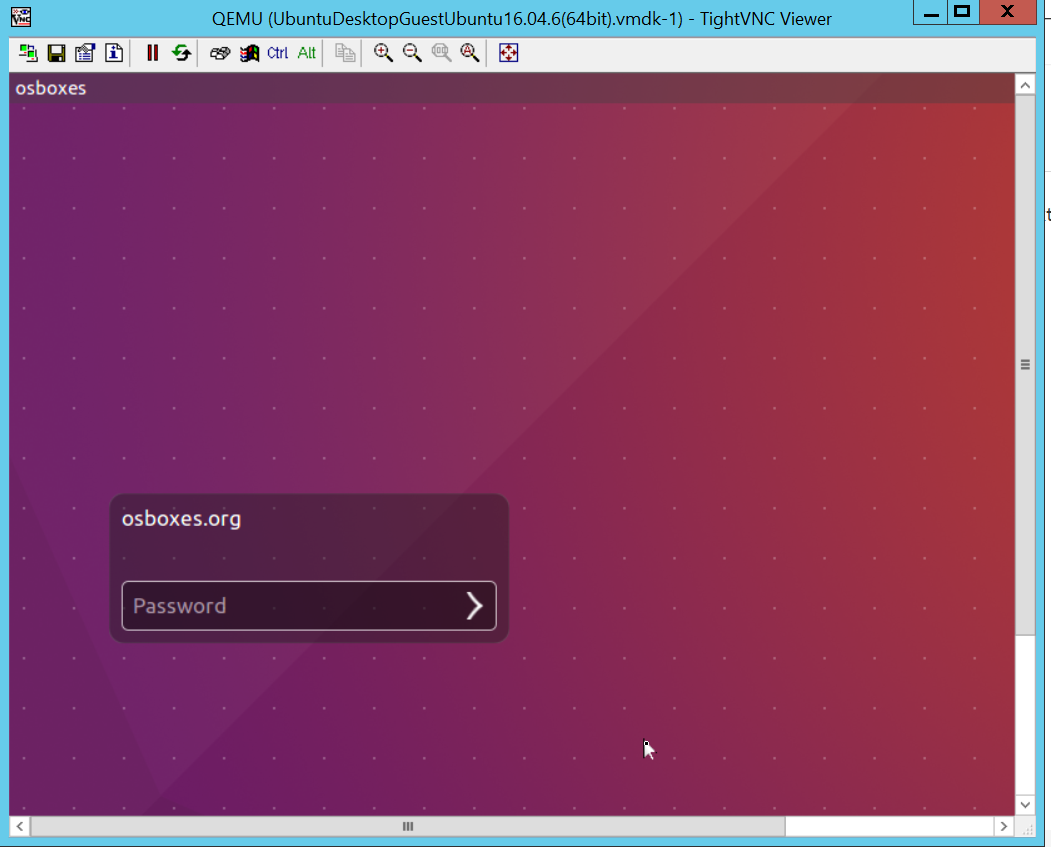
After login, I can set the network interface like below. I need to update file in "/etc/network/interfaces".
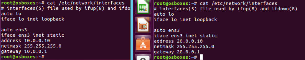
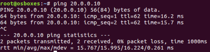
After set both of hosts, I can send ICMP packet each other.
However, there is one more thing necessary. To Join and receive the multicast packet. I need to define the IGMP version on Linux host sometimes. This instruction will be helpful.
| echo "2" >> /proc/sys/net/ipv4/conf/<interface>/force_igmp_version |
In my case, Host 2 and Host 3 will be receiver, therefore it will be like below

3. Configuraton for Multicast environment.
3-1. Configure for default multicast
In fact, I have already done for multicast routing, if you follow sample configuration. This instruction will be helpful to understand how to configure.
| S1 | S2 | S3 | S4 |
|
conf t ! feature pim ! inter lo 1 ip address 99.99.99.99/32 ip router ospf 1 area 0.0.0.0 ip ospf network point ip pim sparse-mode no shutdown exit ! ip pim rp-address 99.99.99.99 ! inter eth 1/1, eth 1/2, eth 1/3 ip pim sparse-mode exit ! |
conf t ! feature pim ! inter lo 1 ip address 99.99.99.99/24 ip router ospf 1 area 0.0.0.0 ip ospf network point ip pim sparse-mode no shutdown exit ! ip pim rp-address 99.99.99.99 ! inter eth 1/1, eth 1/2, eth 1/3 ip pim sparse-mode exit ! |
conf t ! feature pim ! ip pim rp-address 99.99.99.99 ! inter eth 1/1, eth 1/2, eth 1/3 ip pim sparse-mode exit ! inter vlan 10 ip pim sparse-mode exit ! |
conf t ! feature pim ! ip pim rp-address 99.99.99.99 ! inter eth 1/1, eth 1/2, eth 1/3 ip pim sparse-mode exit ! inter vlan 20 ip pim sparse-mode exit ! |
Now, I can test multicast routing with sample script. I can get the result like below.

I success to send multicast traffic. However, I still leave MSDP. "99.99.99.99" is the RP which is S1. I worry the S1 fail situation. MSDP is one of good solution. Please read next step.
3-2. Configure for MSDP.
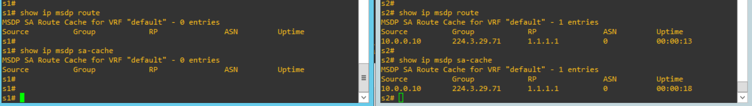
Before, I configure for MSDP. Any information was not shared each other. (S1 and S2 are peer connection for MSDP). I run command "show ip msdp route" and "show ip msdp sa-cache".

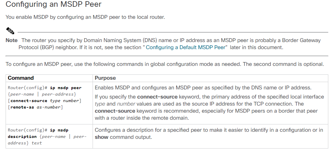
Because of this, the routing information should be registered again on S2, when S1 is failed. Now, I will follow this instruction. At first, I will MSDP configuration to share source information between s1 and s2.
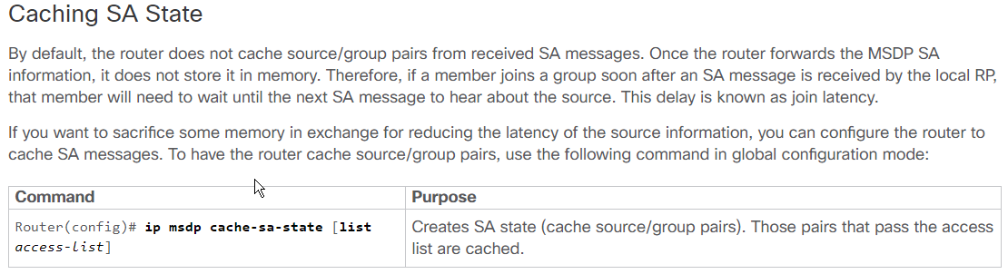

In above, there is "ip msdp cache-sa-state" command for caching. However, there is no command in Nx9000v in my case. Therefore, my configuration should be below.
| s1 | s2 |
|
feature msdp ip msdp originator-id loopback0 ip msdp peer 1.1.1.2 connect-source loopback0 |
feature msdp ip msdp originator-id loopback0 ip msdp peer 1.1.1.1 connect-source loopback0 |
I can check the status with "show ip msdp summary"

I can also verify the status with again "show ip msdp route" and "show ip msdp sa-cache".
In fact, I can not understand this effect.
3-3. Verify the MSDP effect.
Before MSDP configuration, I will shutodown loopback 1 (RP) of S1 switch/router. In S2 switch/router, there is no multicast source information.
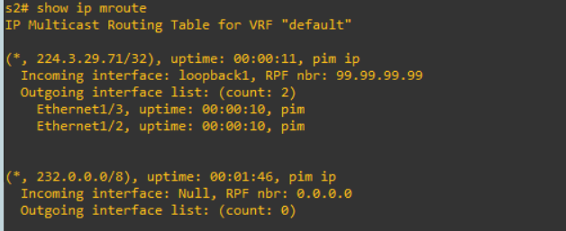
After sender request, the source information is updated. This is normal case
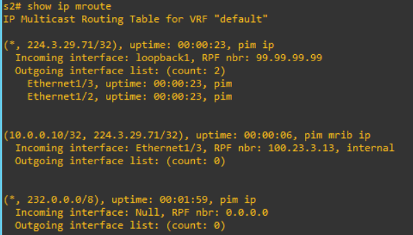
Now, I will configure MSDP. I will shutdown loopback 1 of switch/router S1 again. In S2,

Multicast routing information is updated directly.
Sample Configurations
Reference
[ 1 ] https://www.osboxes.org/ubuntu/#ubuntu-14_04-vmware
[ 2 ] https://docs.gns3.com/1RpM21DdgL2pCNtIrw6e9Yf52tRjYZIe46LMeESl-jy4/
[ 3 ] https://www.cisco.com/c/en/us/td/docs/ios/12_2/ip/configuration/guide/fipr_c/1cfmsdp.html#wp1000963
[ 4 ] https://createnetech.tistory.com/40?category=672584
[ 5 ] https://pymotw.com/2/socket/multicast.html
[ 6 ] https://sites.google.com/site/miclinuxcorner/technology/multicast-routing
[ 7 ] https://www.cisco.com/c/en/us/support/docs/ip/ip-multicast/9356-48.html#msdp
'Network Engineering > Basic Learning' 카테고리의 다른 글
| How does the OSPF cost work? (0) | 2019.07.18 |
|---|---|
| How to work BGP synchronize and next hop self with Nexus? (0) | 2019.07.11 |
| What is basic BGP community concept? (0) | 2019.06.18 |
| How SSL/TLS handshake can be done? (0) | 2018.12.18 |
| How to calculate sequence number of the TCP/IP packets? (0) | 2018.12.17 |