How to outbound external connection of GN3 devices over remote server?
I use GNS3 simulator to study network feature sometimes. There is many instruction over internet. In this post, I will introduce how to use NAT fuction to connect to interet for outbound traffic.
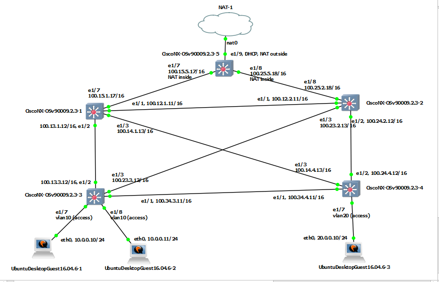
This is the my environment to re-produce in this post.
2. About NAT appliance (DHCP feature).
In GNS3, there is NAT appliance. It has the role to connect the physical interface on remote server virtually. This NAT appliance offers DHCP feature to assign IP address. This IP address determined the next hop against the Cisco switch/router. Thus, the Cisco switch/router should have DHCP feature.
feature dhcp
ip route 0.0.0.0/0 192.168.122.1
no ip dhcp relay
no ipv6 dhcp relay
interface Ethernet1/1
no switchport
ip address dhcp
no shutdown
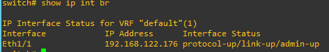
After this configuration, I can verify the interface status with "show ip int br" command
And "ip route 0.0.0.0/0 192.168.122.1" is written. In the Linux host (remote server), I can see the interfaces like below.
With this interfaces, the packet will transfer to external side. I can see the masqurade rule in "iptables table" like below.
Now, I can send traffic to outside on switch 1. Please noteh that it is not possible on switch 2.
switch 1(config)#ip domain-lookup
switch 1(config)# ping 8.8.8.8 PING 8.8.8.8 (8.8.8.8): 56 data bytes 64 bytes from 8.8.8.8: icmp_seq=0 ttl=53 time=19.257 ms 64 bytes from 8.8.8.8: icmp_seq=1 ttl=53 time=2.484 ms
3. Configuration NAT Inside and Outside
Switch 1 can send the packet to outside, however switch 2 can not. Because "192.168.122.0/24" network can only be masquraded in the remote server. This is the reason why the switch 1 has NAT feature. In this instruction, there is the explation for Cisco NAT concept.
Inside source translation is for inside --> outside traffic. Outside source translation is for outside --> inside traffic. At first, I will make the direction on Cisco switch 1.
feature nat
interface Ethernet1/1 no switchport ip address dhcp ip nat outside no shutdown
interface Ethernet1/2 no switchport ip address 172.12.1.12/16 ip nat inside no shutdown
4. Create Rule (NAT Policy) for outbound traffic.
In this post, I handle only outbound traffic. The main factor is that IP address for all traffic to outside should be changed with Switch 1 interface ethernet 1/1 IP address. In this post, It will be useful. I want all traffic to be sent.
ip access-list 1 10 permit ip any any
ip nat inside source list 1 interface Ethernet1/1 overload
5. Configure inside network (Switch 2).
So far, I made NAT firewall. From this part, it can assume internet network. However, I only use single switch/router simply.
ip route 0.0.0.0/0 172.12.1.12
interface Ethernet1/2
no switchport
ip address 172.12.2.12/16
no shutdown
This is normal configuration. There is nothing special. After default configuration. I can verify the outbound connection like below over switch 2.
I will make full-mesh connectivity. There are four switch/router. I will name as s1, s2, s3 and s4. On those switch/router, I will run OSPF routing to announce loopback addresses for Router ID and RP point.
s1
s2
s3
s4
conf t ! switchname s1 ! feature ospf router ospf 1 router-id 1.1.1.1 exit ! inter lo 0 ip add 1.1.1.1/32 ip router ospf 1 area 0.0.0.0 no shut exit ! inter et 1/7 no sw ip add 100.15.1.17/16 no shut exit ! inter et 1/1 no sw ip add 100.12.1.11/16 ip router ospf 1 area 0.0.0.0 no shut exit ! inter et 1/2 no sw ip add 100.13.1.12/16 ip router ospf 1 area 0.0.0.0 no shut exit ! inter et 1/3 no sw ip add 100.14.1.13/16 ip router ospf 1 area 0.0.0.0 no shut exit ! ip route 0.0.0.0/0 100.15.5.17 ip route 0.0.0.0/0 100.12.2.11 100 end !
conf t ! switchname s2 ! feature ospf router ospf 1 router-id 2.2.2.2 exit ! inter lo 0 ip add 2.2.2.2/32 ip router ospf 1 area 0.0.0.0 no shut exit ! inter et 1/8 no sw ip add 100.25.2.18/16 no shut exit ! inter et 1/1 no sw ip add 100.12.2.11/16 ip router ospf 1 area 0.0.0.0 no shut exit ! inter et 1/2 no sw ip add 100.24.2.12/16 ip router ospf 1 area 0.0.0.0 no shut exit ! inter et 1/3 no sw ip add 100.23.2.13/16 ip router ospf 1 area 0.0.0.0 no shut exit ! ip route 0.0.0.0/0 100.25.5.18 ip route 0.0.0.0/0 100.12.1.11 100 end !
conf t ! switchname s3 ! feature ospf router ospf 1 router-id 3.3.3.3 exit ! inter lo 0 ip add 3.3.3.3/32 ip router ospf 1 area 0.0.0.0 no shut exit ! inter et 1/1 no sw ip add 100.34.3.11/16 ip router ospf 1 area 0.0.0.0 no shut exit ! inter et 1/2 no sw ip add 100.13.3.12/16 ip router ospf 1 area 0.0.0.0 no shut exit ! inter et 1/3 no sw ip add 100.23.3.13/16 ip router ospf 1 area 0.0.0.0 no shut exit ! ip route 0.0.0.0/0 1.1.1.1 ip route 0.0.0.0/0 2.2.2.2 ! vlan 10 name vlan10 exit ! feature interface-vlan inter vlan10 no shut ip add 10.0.0.1/24 exit ! inter et 1/7, et 1/8 sw mode ac sw ac vlan 10 no shut exit !
---------------------------------- ! conf t ! inter vlan 10 ip router ospf 1 area 0.0.0.0 exit ! ---------------------------------- conf t ! feature pim ! ip pim rp-address 99.99.99.99 ! inter eth 1/1, eth 1/2, eth 1/3 ip pim sparse-mode exit ! inter vlan 10 ip pim sparse-mode exit !
conf t ! switchname s4 ! feature ospf router ospf 1 router-id 4.4.4.4 exit ! inter lo 0 ip add 4.4.4.4/32 ip router ospf 1 area 0.0.0.0 no shut exit ! inter et 1/1 no sw ip add 100.34.4.11/16 ip router ospf 1 area 0.0.0.0 no shut exit ! inter et 1/2 no sw ip add 100.24.4.12/16 ip router ospf 1 area 0.0.0.0 no shut exit ! inter et 1/3 no sw ip add 100.14.4.13/16 ip router ospf 1 area 0.0.0.0 no shut exit ! ip route 0.0.0.0/0 1.1.1.1 ip route 0.0.0.0/0 2.2.2.2 ! vlan 20 name vlan20 exit ! feature interface-vlan inter vlan20 no shut ip add 20.0.0.1/24 exit ! inter et 1/7 sw mode ac sw ac vlan 20 no shut exit !
---------------------------------- ! conf t ! inter vlan 20 ip router ospf 1 area 0.0.0.0 exit ! ---------------------------------- conf t ! feature pim ! ip pim rp-address 99.99.99.99 ! inter eth 1/1, eth 1/2, eth 1/3 ip pim sparse-mode exit ! inter vlan 20 ip pim sparse-mode exit !
In s1 and s2, there are 2 kinds of loopback addresses. One is for the switch/router ID, the other is for the RP address. For loopback address for RP, I will utilize "ghost loopback address" method. Please look at the loopback interface 1 in s1 and s2.
s1
s2
conf t ! feature pim ! inter lo 1 ip address 99.99.99.99/32 ip router ospf 1 area 0.0.0.0 ip ospf network point ip pim sparse-mode no shutdown exit ! ip pim rp-address 99.99.99.99 ! inter eth 1/1, eth 1/2, eth 1/3 ip pim sparse-mode exit !
conf t ! feature pim ! inter lo 1 ip address 99.99.99.99/24 ip router ospf 1 area 0.0.0.0 ip ospf network point ip pim sparse-mode no shutdown exit ! ip pim rp-address 99.99.99.99 ! inter eth 1/1, eth 1/2, eth 1/3 ip pim sparse-mode exit !
S1 is the main RP server in normal status. However, it will be changed to s2 when S1 is failed without IP address change. Because of this, I need MSDP (Multicast Source Discovery Protocol). I will handle in later. To announce the network with subnet of loopback interface into OSPF, "Point to Point" is necesary. Now I can see the routing table on S3 and S4 switch/router.
s3# show ip route ospf-1
s4# show ip route ospf-1
1.1.1.1/32, ubest/mbest: 1/0 *via 100.13.1.12, Eth1/2, [110/41], 3d00h, ospf-1, intra 2.2.2.2/32, ubest/mbest: 1/0 *via 100.23.2.13, Eth1/3, [110/41], 3d00h, ospf-1, intra 4.4.4.4/32, ubest/mbest: 1/0 *via 100.34.4.11, Eth1/1, [110/41], 3d00h, ospf-1, intra 20.0.0.0/24, ubest/mbest: 1/0 *via 100.34.4.11, Eth1/1, [110/80], 03:33:46, ospf-1, intra 99.99.99.0/24, ubest/mbest: 1/0 *via 100.23.2.13, Eth1/3, [110/41], 00:44:41, ospf-1, intra 99.99.99.99/32, ubest/mbest: 1/0 *via 100.13.1.12, Eth1/2, [110/41], 00:44:41, ospf-1, intra 100.12.0.0/16, ubest/mbest: 2/0 *via 100.13.1.12, Eth1/2, [110/80], 3d00h, ospf-1, intra *via 100.23.2.13, Eth1/3, [110/80], 3d00h, ospf-1, intra 100.14.0.0/16, ubest/mbest: 2/0 *via 100.13.1.12, Eth1/2, [110/80], 3d00h, ospf-1, intra *via 100.34.4.11, Eth1/1, [110/80], 3d00h, ospf-1, intra 100.24.0.0/16, ubest/mbest: 2/0 *via 100.23.2.13, Eth1/3, [110/80], 3d00h, ospf-1, intra *via 100.34.4.11, Eth1/1, [110/80], 3d00h, ospf-1, intra
1.1.1.1/32, ubest/mbest: 1/0 *via 100.14.1.13, Eth1/3, [110/41], 3d00h, ospf-1, intra 2.2.2.2/32, ubest/mbest: 1/0 *via 100.24.2.12, Eth1/2, [110/41], 3d00h, ospf-1, intra 3.3.3.3/32, ubest/mbest: 1/0 *via 100.34.3.11, Eth1/1, [110/41], 3d00h, ospf-1, intra 10.0.0.0/24, ubest/mbest: 1/0 *via 100.34.3.11, Eth1/1, [110/80], 03:34:26, ospf-1, intra 99.99.99.0/24, ubest/mbest: 1/0 *via 100.24.2.12, Eth1/2, [110/41], 00:45:13, ospf-1, intra 99.99.99.99/32, ubest/mbest: 1/0 *via 100.14.1.13, Eth1/3, [110/41], 00:45:13, ospf-1, intra 100.12.0.0/16, ubest/mbest: 2/0 *via 100.14.1.13, Eth1/3, [110/80], 3d00h, ospf-1, intra *via 100.24.2.12, Eth1/2, [110/80], 3d00h, ospf-1, intra 100.13.0.0/16, ubest/mbest: 2/0 *via 100.14.1.13, Eth1/3, [110/80], 3d00h, ospf-1, intra *via 100.34.3.11, Eth1/1, [110/80], 3d00h, ospf-1, intra 100.23.0.0/16, ubest/mbest: 2/0 *via 100.24.2.12, Eth1/2, [110/80], 3d00h, ospf-1, intra *via 100.34.3.11, Eth1/1, [110/80], 3d00h, ospf-1, intra
In red text above, "100.100.100.100" is the RP address for multicast. At this time, the destination should be s1. It will be changed to s2 by "100.100.100.0/24", when s1 is failed.
2-2. Configure the Host (PC, Labtop) network.
s3 and s4 is the gateway for each host network. In my scenario, I will use "10.0.0.0/24" for PC1 and "20.0.0.0/24" for PC2.
I have already done for the gateway above.
S3
S4
!
conf t
!
inter vlan 10
ip router ospf 1 area 0.0.0.0
exit
!
inter eth 1/1, eth 1/2, eth 1/3
ip pim sparse-mode
exit
!
inter vlan 10
ip pim sparse-mode
exit
!
!
conf t
!
inter vlan 20
ip router ospf 1 area 0.0.0.0
exit
!
inter eth 1/1, eth 1/2, eth 1/3
ip pim sparse-mode
exit
!
inter vlan 20
ip pim sparse-mode
exit
!
Now I will configure the PC network interface. In my case I will use "Ubuntu Desktop". In this instruction, I can see how to install "ubuntu" in GNS3. After installation, I can open the console like below.
After login, I can set the network interface like below. I need to update file in "/etc/network/interfaces".
After set both of hosts, I can send ICMP packet each other.
However, there is one more thing necessary. To Join and receive the multicast packet. I need to define the IGMP version on Linux host sometimes. This instruction will be helpful.
Now, I can test multicast routing with sample script. I can get the result like below.
I success to send multicast traffic. However, I still leave MSDP. "99.99.99.99" is the RP which is S1. I worry the S1 fail situation. MSDP is one of good solution. Please read next step.
3-2. Configure for MSDP.
Before, I configure for MSDP. Any information was not shared each other. (S1 and S2 are peer connection for MSDP). I run command "show ip msdp route" and "show ip msdp sa-cache".
Because of this, the routing information should be registered again on S2, when S1 is failed. Now, I will follow this instruction. At first, I will MSDP configuration to share source information between s1 and s2.
In above, there is "ip msdp cache-sa-state" command for caching. However, there is no command in Nx9000v in my case. Therefore, my configuration should be below.
s1
s2
feature msdp
ip msdp originator-id loopback0
ip msdp peer 1.1.1.2 connect-source loopback0
feature msdp
ip msdp originator-id loopback0
ip msdp peer 1.1.1.1 connect-source loopback0
I can check the status with "show ip msdp summary"
I can also verify the status with again "show ip msdp route" and "show ip msdp sa-cache".
In fact, I can not understand this effect.
3-3. Verify the MSDP effect.
Before MSDP configuration, I will shutodown loopback 1 (RP) of S1 switch/router. In S2 switch/router, there is no multicast source information.
After sender request, the source information is updated. This is normal case
Now, I will configure MSDP. I will shutdown loopback 1 of switch/router S1 again. In S2,
Multicast routing information is updated directly.
At first I need to prepare the hosts for Kubernetes components. In my case, I have 5 nodes, one for master, one for external etcd and three for workers. After I prepare these nodes. I need to update "/etc/hostname" and "/etc/hosts" files propertly. For example, I have to change hostname to "m1" as master node.
Kubernetes use Docker engine. Therefore, I need to install Docker. I will follow this instruction. In my case, I will run this kubernetes over Ubuntu 16.04. This is overview.
From this instruction, I will change this driver from "cgroupsfs" to "systemd". This change affect lots of issue during Kubernetes installation. Therefore I need to remember this.
Kubelet (daemon on each node has the role to handle conatiner), kubeadm (daemon on each node has the role to setup master and workers) and kubectl (daemon on each node has the role to manage the cluster) are necessary components.
After installation, I need to check the directories which are created during the installation. "/etc/kubernetes/" and "/var/lib/kubelet/pki/" and "/etc/systemd/system/kubelet.service.d/" are created.
# ls /etc/kubernetes/ manifests # ls /etc/kubernetes/manifests/ # ls /var/lib/kubelet/ pki # ls /var/lib/kubelet/pki/ kubelet.crt kubelet.key # ls /etc/systemd/system/kubelet.service.d/ 10-kubeadm.conf
To work Kubernetes normally, Kubelet work normally at first. I can check the status with "systemctl status kubelet". At this moment, it is not activate.
# systemctl status kubelet
kubelet.service - kubelet: The Kubernetes Node Agent
May 22 10:59:59 e1 systemd[1]: kubelet.service: Main process exited, code=exited, status=255/n/a
May 22 10:59:59 e1 systemd[1]: kubelet.service: Unit entered failed state.
May 22 10:59:59 e1 systemd[1]: kubelet.service: Failed with result 'exit-code'.
To see more details, I will look at the logs in "/var/log/syslog". From logs, I can check I need "config.yaml" file. Keep this issue and go to next step. This file will be created with "kubectl init" command later.
# tail -f /var/log/syslog
systemd[1]: kubelet.service: Service hold-off time over, scheduling restart.
systemd[1]: Stopped kubelet: The Kubernetes Node Agent.
systemd[1]: Started kubelet: The Kubernetes Node Agent.
kubelet[12865]: F0522 10:59:49.732907 12865 server.go:193] failed to load Kubelet config file /var/lib/kubelet/config.yaml, error failed to read kubelet config file "/var/lib/kubelet/config.yaml", error: open /var/lib/kubelet/config.yaml: no such file or directory
systemd[1]: kubelet.service: Main process exited, code=exited, status=255/n/a
systemd[1]: kubelet.service: Unit entered failed state.
systemd[1]: kubelet.service: Failed with result 'exit-code'.
I need to match the cgroup driver with the value "systemd". In the instruction, there is the comment like below.
However there are no "/etc/default/kubelet" and "/var/lib/kubelet/kubeadm-flags.env". So I can not update this with this instruction. Please look at the result from "systemctl status kubelet". I can see "/etc/systemd/system/kubelet.service.d/10-kubeadm.conf". This is the loaded file when kubelet is started.
# Note: This dropin only works with kubeadm and kubelet v1.11+
I will add the red text, Environment="KUBELET_EXTRA_ARGS=--cgroup-driver=systemd". And restart the kubelet with "systemctl daemon-reload" and "systemctl restart kubelet". However, it is still not activated due to no config.yaml.
3. Install external etcd cluster
I have alread posted in here. To create the etcd cluster, It is not easy. However, I can make these with this instruction easliy. This etcd will be created as one of container application which are managed by Kubernetes. On the external etcd node, I have to run command below.
The file name start with 20-etcd-service-manager.conf due to "20", so it has higher priority rather than 10-kubeadm.conf. After running this, I can check the "systemctl status kubelet" and "/var/log/syslog". The kubelet does not works with some error. This error is different from above. The first error above is happend after 10-kubeadm.conf loading. However this error is happend during 20-etcd-service-manager.conf loading. So I have to solve this error at first.
tail -f /var/log/syslog
systemd[1]: kubelet.service: Service hold-off time over, scheduling restart.
systemd[1]: Stopped kubelet: The Kubernetes Node Agent.
systemd[1]: Started kubelet: The Kubernetes Node Agent.
kubelet[28517]: I0522 14:05:31.498194 28517 plugins.go:103] No cloud provider specified.
kubelet[28517]: W0522 14:05:31.498229 28517 server.go:556] standalone mode, no API client
kubelet[28517]: W0522 14:05:31.598549 28517 server.go:474] No api server defined - no events will be sent to API server.
kubelet[28517]: I0522 14:05:31.598601 28517 server.go:625] --cgroups-per-qos enabled, but --cgroup-root was not specified. defaulting to /
kubelet[28517]: F0522 14:05:31.599231 28517 server.go:265] failed to run Kubelet: Running with swap on is not supported, please disable swap! or set --fail-swap-on flag to false. /proc/swaps contained: [Filename#011#011#011#011Type#011#011Size#011Used#011Priority /dev/sda2 partition#0111996796#0110#011-1]
systemd[1]: kubelet.service: Main process exited, code=exited, status=255/n/a
systemd[1]: kubelet.service: Unit entered failed state.
systemd[1]: kubelet.service: Failed with result 'exit-code'.
There are some error and warning messages. To solve this, I have to create "kubeadmcfg.yaml" from this instruction. In my case, I will difference file name like below
"controlPlaneEndpoint: 147.75.94.251:6443" is master IP address and Port for API server. This parameter solve this warning "No api server defined - no events will be sent to API server.". 147.75.92.69 ip address is external etcd node interface IP addresss which is announced for outside. In this yaml file, some options are included. Therefore, I have to revise 20-etcd-service-manager.conf file like below.
Even if I added more options in yaml file, I do not handle root cause why the kubelet fail. In the syslog, "failed to run Kubelet: Running with swap on is not supported, please disable swap! or set --fail-swap-on flag to false" is the main reason. To solve this, there are 3 option.
"swapoff -a" is temporary option. Comment "swap" in "/etc/fstab" is permenant option. Adding "--fail-swap-on=false" in 20-etcd-service-manager.conf is another permenant option. After then, the status of kubelet will be like this.
Now, I am ready to deploy etcd container deployment. I need certificate and private key for etcd cluster to work well. These values are located in "/etc/kubernetes/pki/etcd". However, you do not have this directory at this time. As the instruction, these file will be generated with command below.
# kubeadm init phase certs etcd-ca [certs] Generating "etcd/ca" certificate and key # ls /etc/kubernetes/pki/etcd/ ca.crt ca.key
If you are want to make cluster of etcd nodes, I have copy these files on each etcd nodes. However, it is not enough to work well. I need more certiface and key.
after then, serveral key will be generated. In fact, some of key is not necessary if you run single external etcd node. Now, I can run etcd container with command below
# kubeadm init phase etcd local --config=external-etcd-cfg.yaml
# docker ps CONTAINER ID IMAGE COMMAND CREATED STATUS PORTS NAMES f7f427f30a04 2c4adeb21b4f "etcd --advertise-cl…" 16 minutes ago Up 16 minutes k8s_etcd_etcd-e1_kube-system_9a37a797efa5968588eac7b51458eecc_0 5686bb62b14f k8s.gcr.io/pause:3.1 "/pause" 16 minutes ago Up 16 minutes k8s_POD_etcd-e1_kube-system_9a37a797efa5968588eac7b51458eecc_0
# docker exec f7f427f30a04 etcdctl --cert-file /etc/kubernetes/pki/etcd/peer.crt --key-file /etc/kubernetes/pki/etcd/peer.key --ca-file /etc/kubernetes/pki/etcd/ca.crt --endpoints https://147.75.92.69:2379 cluster-health member d3b00bc687dc09ae is healthy: got healthy result from https://147.75.92.69:2379 cluster is healthy
I can also check the health status.
4. Install master nodes
There are 2 instructions for master node, single master and cluser masters. To setup the master node, I need configuration file. I will refer from this instruction. This is the sample configuration yaml file what I have
Sometimes, some module are not loaded. So I need to do manually with "modeprobe". If these module are not loaed when kubeadm init is started, I can see this message "kernel modules are not loaded: [ip_vs ip_vs_rr ip_vs_wrr ip_vs_sh]"
Now, it will load the file "/etc/systemd/system/kubelet.service.d/10-kubeadm.conf".
After this, I can use "kubectl" command. Sometimes, master status can be "NotReady". At this time, I should check the status of pods with "kubectl get pods --all-namespace"
# kubectl get nodes
NAME STATUS ROLES AGE VERSION
m1 NotReady master 4m43s v1.14.2
From this instruction, I need to POD network to solve this issue.
There is something strange. "cgroupDriver: cgroupfs" is strange. It should be "systemd", becuase I update "Environment="KUBELET_EXTRA_ARGS=--cgroup-driver=systemd" in "/etc/systemd/system/kubelet.service.d/10-kubeadm.conf". I think it is not work. I will update for this
However, this is not all of things. I have alread made external etcd. I have not configure for this yet. Default, etcd conatiner is located on each master node. They are not clustered.
Now, I will run "kubeadm reset" and "kubeadm init" again. Please note that the certificate and key will be remove when I run kubeadm reset. Therefore, I need to copy again from etcd node
error execution phase preflight: [preflight] Some fatal errors occurred: [ERROR ExternalEtcdVersion]: couldn't load external etcd's server certificate /etc/kubernetes/pki/etcd/ca.crt: open /etc/kubernetes/pki/etcd/ca.crt: no such file or directory [ERROR ExternalEtcdClientCertificates]: /etc/kubernetes/pki/etcd/ca.crt doesn't exist [ERROR ExternalEtcdClientCertificates]: /etc/kubernetes/pki/apiserver-etcd-client.crt doesn't exist [ERROR ExternalEtcdClientCertificates]: /etc/kubernetes/pki/apiserver-etcd-client.key doesn't exist [preflight] If you know what you are doing, you can make a check non-fatal with `--ignore-preflight-errors=...`
After I copy the certificate and key, I can check the status again
It is almost same. I need docker engin and kubeadm, kubectl, kubelet. I have already explain about these above. After creating master node, I can see the message like below
There are some preparation. Docker and Etcd should be installed before. Here is instruction for installation of Docker. I will install community engine on 2 nodes running "ubuntu 16.04".
I will make configuration file to create the network topology.
vi flannel-network-config.json
{
"Network": "172.16.0.0/12",
"SubnetLen": 24,
"SubnetMin": "172.16.16.0",
"SubnetMax": "172.31.247.0",
"Backend": {
"Type": "vxlan",
"VNI": 172,
"Port": 8889
}
}
In this documentation, there are the meaning of the above parameters. Especially, "SubnetLen" is IP address range allocated in each host. Flannel use the configuration from Etcd, /coreos.com/network/config. I will set the configuration on Node 1
# At node 1
cd etcd-v3.0.12-linux-amd64/
~/etcd-v3.0.12-linux-amd64$ ./etcdctl set /coreos.com/network/config < ../flannel-network-config.json
I can check if the configuration is set or not on Node 2.
# At node 2
cd etcd-v3.0.12-linux-amd64/
~/etcd-v3.0.12-linux-amd64$ ./etcdctl get /coreos.com/network/config | jq .
{
"Network": "172.16.0.0/12",
"SubnetLen": 24,
"SubnetMin": "172.16.16.0",
"SubnetMax": "172.31.247.0",
"Backend": {
"Type": "vxlan",
"VNI": 172,
"Port": 8889
}
}
Now, I am ready to start the flannel. Before start flannel, I have to look at my network interface status.
# At node 1
nohup sudo ./flanneld -iface=bond0 &
# At node 2
nohup sudo ./flanneld -iface=bond0 &
After start flannel, I can see new interface which is named with "flannel.VNI". In this case, It should be flannel.172.
flannel.172 Link encap:Ethernet HWaddr 82:41:de:d4:77:d3
~/etcd-v3.0.12-linux-amd64# ./etcdctl ls /coreos.com/network/subnets
/coreos.com/network/subnets/172.16.68.0-24
/coreos.com/network/subnets/172.16.75.0-24
This mean that each host has these subnets each. I can see more detail.
cd etcd-v3.0.12-linux-amd64/
~/etcd-v3.0.12-linux-amd64# ./etcdctl get /coreos.com/network/subnets/172.16.68.0-24 | jq .
{
"PublicIP": "147.75.65.63",
"BackendType": "vxlan",
"BackendData": {
"VtepMAC": "7a:ac:15:15:2b:61"
}
}
This is configuration for the flannel. I can also see the what flannel network is assigned with "/var/run/flannel/subnet.env". Please note that this file will be used for next step, docker daemon configuration.
cat /var/run/flannel/subnet.env
FLANNEL_NETWORK=172.16.0.0/12
FLANNEL_SUBNET=172.16.68.1/24
FLANNEL_MTU=1450
FLANNEL_IPMASQ=false
3. Docker daemon configuration.
Docker does not use flannel default. It has swarm mode to make overlay network. Therefore, it is necessary to change to use this flannel as default network module. At first, I have to stop the Docker daemon on each hosts, node1 and node2.
# Node 1 and Node 2
sudo service docker stop
I will restart Docker daemon with this flannel configuration.
Before restart Docker daemon, there is "docker0" interface default which has "172.17.0.1" IP address. It will be changed with the network what I defined.
# Before restart with flannel configuration
ifconfig docker0
docker0 Link encap:Ethernet HWaddr 02:42:f6:10:ac:49
sudo docker run -d --name test1 busybox sh -c "while true; do sleep 3600; done"
# At the node 2
ssudo docker run -d --name test2 busybox sh -c "while true; do sleep 3600; done"
Depends on the container properties, the container can be stopped after exit. "sh -c "while true; do sleep 3600; done" make this container keep alive for 1 hour. It is enough for the test.
5. Analysis container networks.
In this post, I will explain how to work in docker swarm mode. It is good to analysis the network topology of docker. At first, go to "/var/run/docker", there is the "netns" directory. There is the network configuration of the container.
# At node 1 and node 2
cd /var/run/
ln -s docker/netns/ netns
After this symbolic link, I can see the network namespace list like below. "ip netns list" show the namespace ID.
ip netns list
faf9928b897f (id: 0)
I can see more detail information with this ID. "ip netns exec" show the same result with "docker exec". Thus I can see the same result with "docker exec test1 ip -d addr show"
# At the Node 1
ip netns exec b5380e6b336a ip -d addr show
1: lo: <LOOPBACK,UP,LOWER_UP> mtu 65536 qdisc noqueue state UNKNOWN group default qlen 1
inet 172.16.68.2/24 brd 172.16.68.255 scope global eth0
valid_lft forever preferred_lft forever
6. Test and Troubleshooting
Now, I have know that "172.16.75.2" is container IP address on Node 1 and "172.16.68.2" is container IP address on Node 2. Flannel offers the overlay network between hosts. So, I will send ICMP (ping) from node1 to node2
ip netns exec b5380e6b336a ping 172.16.68.2
PING 172.16.68.2 (172.16.68.2) 56(84) bytes of data.
^C
--- 172.16.68.2 ping statistics ---
6 packets transmitted, 0 received, 100% packet loss, time 5040ms
Hmm. It does not work. From Docker 1.13 default iptables policy for FORWARDING is DROP,
# At Node 1 and Node 2
sudo iptables -P FORWARD ACCEPT
Wow, I can send ICMP each other.
ip netns exec b5380e6b336a ping 172.16.68.2
ip netns exec b5380e6b336a ping 172.16.68.2 -c 4
PING 172.16.68.2 (172.16.68.2) 56(84) bytes of data.
64 bytes from 172.16.68.2: icmp_seq=1 ttl=62 time=0.364 ms
64 bytes from 172.16.68.2: icmp_seq=2 ttl=62 time=0.310 ms
64 bytes from 172.16.68.2: icmp_seq=3 ttl=62 time=0.319 ms
64 bytes from 172.16.68.2: icmp_seq=4 ttl=62 time=0.308 ms
--- 172.16.68.2 ping statistics ---
4 packets transmitted, 4 received, 0% packet loss, time 2998ms
At first, Client send the "Client Hello" packet. In this packet, there are three important information. Random number, Session ID and Cipher suites.
Random number is used to generate "pre-master key" with another random number from server. This "pre-master key" will be used to generate "master key" which encrypt and decrypt the packets.
Cipher suites is the list which the client can support. Thus, the server will select one of this lists.
2. Server Hello.
After receive the client hello, server send the "Server Hello" packet to client. In this packet, there are three important information. Random number, Cipher suite and Certificate with Public key.
Random number is used to generate "pre-master key" with another random number from client.
Cipher suite is the selected item which is one of list from client.
Certificates is the very important parameters. In this values, "Public Key" is included. This "Public Key" is used to encrypt the "pre-master key" before transfer to server.
3. Client Key Exchange
In this step, Client know both random values of client and server. Therefore, client generate the "Pre-master key". Also, client can know public key because of the received certificates. So, client sent the packet which "Pre-master key" is included in. It is encrypted by public key.
4. Server Response.
Finally, the server knows "pre-master key", after decrypting received packet. The server and client will be generate "master key" each by some algorithm. This "master key" is used for encrypt and decrypt the data packet.
5. Data Packet with Encryption.
So, the Data packets are encrypted by this master key. I can see the SSL layer in the packets like below. Data will be encrypted.
How to calculate sequence number of the TCP/IP packets?
I am the network engineer. Recently, I have some change to remember the sequence number of the TCP/IP packets. Someone include me think that this is not easy.
1. General Packet Structure.
IP header and TCP header have generally 20 Byte size of the packets. Data payloads can be maximum 1460 Byte size of the packets.
MSS is the data size, which determine how much can be send at one time. MTU is sum of TCP, IP and MSS (Data).
MSS = Maximum TCP Segment Size in one Packet – usually it is 1460 + 20 (TCP Header) + 20 (IP Header) = MTU =1500 + 18 (DLC Header) and you have a full frame of 1518 bytes.
2. IP header Structure
I have told "IP header is 20 Byte". However, IP header is not fixable. It can be increased by optional values up to 60 Byte. In this header, there are three point which I need to focus on.
Length field shows how much size of IP header. Identification field is one of mark. This is the unique value which is not changed from source to destination. In this link, I can see more detail of the Protocol field.
3. TCP header structure.
TCP header is also not fixable. It can be max 60 Byte. In TCP header, there are sequence number, acknowledge number and window size value.
Windows size value is determined by server environment, such as allocated memory of operating system. It can be increased or decreased. If I suffer from "Zero Window" issue, I have to check the buffer size of host.
4. DLC header structure.
This header shows MAC address generally. In Ethernet field, 0x0800 means IPv4 and 0x08dd means IPv6.
5. Packet sequence analysis for SYN and FIN
For SYN-ACK / FIN-ACK handshake, it is important to add +1 value, even if length of data is zero. Client sent packet with sequence number 0. Therefore, the expect ACK number should 1. Server will send the packet with sequence number 0 and ACK number is 1. For this packet, the expect ACK number should also is 1. Finally, client send last ACK packet with sequence number 1 and ACK number 1.
6. Packet sequence analysis for Data
For Data, It is little bit different with above. It add only length of data. Look at the below. Fist, sequence number 380 + data length 213 is Expect ACK with number 593.
Second, sequence number 1306 + data length 373 is 1679 with ACK 593 which come from above.
Final, sequence number 593 which equals with ACK number will transfer with ACK 1679.
7. Optional,SACK (Selective ACK)
For effective transmission, the selective ACK mechanism is existed. Look at the below. 172.18.0.74 is sender. This sender send the packet with sequence number, 5943, 7403, 8863, 10323, 11784, 13243, and 14703. The data length is 1460. Thus, there is no loss to transfer.
However, Loot at the below. At this time, ACK number is important value. "ACK=10323, SLE=13243, SRE=14703" message means 11783 packet does not exist in the receiver.
In the last, re-transmission for sequence 11783 is happen. The ACK number with 11783 is shown.
vxlan id 42 remote 147.75.73.195 local 147.75.75.185 dev bond0 srcport 0 0 dstport 4789 ageing 300 addrgenmode eui64
3.Add VXLAN interface on Linux Bridge
However, it is not enough to communicate over tunnel. In this case, the traffic of “192.168.10.0/24” can not pass over the Linux Bridge. Thus, It is necessary for VXLAN interface to attach on the Linux Bridge.
# brctl addif vbr0 vxlan42
# ifconfig vxlan42 up
# brctl show
bridge name bridge id STP enabled interfaces
vbr0 8000.aa6ffcd67a96 no vxlan42
4.Testing and analysis
I will do ping with one of “192.168.10.0/24” IP address.
# ping 192.168.10.21
PING 192.168.10.21 (192.168.10.21) 56(84) bytes of data.
64 bytes from 192.168.10.21: icmp_seq=1 ttl=64 time=0.291 ms
64 bytes from 192.168.10.21: icmp_seq=2 ttl=64 time=0.284 ms
64 bytes from 192.168.10.21: icmp_seq=3 ttl=64 time=0.314 ms
64 bytes from 192.168.10.21: icmp_seq=4 ttl=64 time=0.317 ms
And I will dump packet during sending the packets. From the result, I can confirm “ICMP packets are encapsulated over VXLAN”
# tcpdump -ni bond0 not port 22 and not port 23
tcpdump: verbose output suppressed, use -v or -vv for full protocol decode
listening on bond0, link-type EN10MB (Ethernet), capture size 262144 bytes
I recently the existence of this “ipvsadm” which used as the load-balancer. “ipvsadm” is referred linux kernel load-balancer, which is also called “LVS, Linux Virtual Server”. This LVS has 3 mode such as DR (Direct Routing), Tunnel and Masquerade. In this post, I will handle DSR and Masquerade (Network Address Translation, NAT).
Direct Routing : The option value is default with “-g”. The packet is send without modifying. The servers receives the packets from “ipvsadm” response to client directly.
Network Address Translation (NAT) : This option is adapted with “-m”. The packet is send with modifying the destination IP address. (The source IP address is not modified). The servers have to response the “ipvsadm”. Usually, The servers indicate “ipvsadm” as the default gateway.
My test environment is set on Ubuntu 16.04. I used AWS IaaS.
1. DR mode
1-1. ipvsadm configuration
Enable the IP forwarding, because the “ipvsadm” has the role to transfer and distribute received packets. To enable, edit “net.ipv4.ip_forward=1“ in “/etc/sysctl.conf” and run “sysctl -p /etc/sysctl.conf” or “sysctl –p” to apply this. It can be done with, echo 1 > /proc/sys/net/ipv4/conf/all/forwarding, alternatively.
Configure virtual server, there are two steps. First, create the virtual server with traffic distribute method such as round-robin. Second, register servers to distribute the packets. ipvsadm -C ipvsadm -A -t 10.10.0.244:80 -s rr ipvsadm -a -t 10.10.0.244:80 -r 10.10.0.233:80 -g After this configuration, I can confirm the status with “ipvsadm –Ln”, “ipvsadm –Lcn”, and “ipvsadm -l –-stats”
“ipvsadm –Ln” show the mapping information with forward method. In this case, the received packet with “10.10.0.244:80” will be routed to “10.10.0.233:80”.
“ipvsadm –Lcn” show the current session information. At this time, there is no con-current connection now.
“ipvsadm -l –-stats” show the information for in/out traffic information.
1-2. Servers configuration
In DR mode, the server received the packet without modifying. And the server response to the client directly. However, the packet drop can be happened in client side, because the client receive the packet from the server with server’s IP address. To resolve this issue, the server need to set the loopback interface with service IP address. In this case, the service IP address should be “10.10.0.244”. ifconfig lo:0 10.10.0.244 netmask 255.255.255.255
LVS Direct Routing works by forwarding packets to the MAC address of servers. In this case, we have to consider “Linux ARP flux” problem. The server should not answer ARP request for “10.10.0.244”. For, this, I added in “/etc/sysctl.conf”. net.ipv4.conf.all.arp_ignore=1 net.ipv4.conf.all.arp_announce=2
1-3. Testing and analysis
Client send the request with “curl http://10.10.0.244” and get the response from server. I dumped the “ipvsadm” and “server”. Loot at the “ipvsadm” result. I can see there is no change of source and destination IP address.
This is something strange. “ipvsadm” has “10.10.0.244”, so it looks like sending to myself. This is the DR mode property, which works by MAC address of servers. Look at the connection information with “ipvsadm –Lcn”, the destination IP address can be shown.
At this time, what happened in the server, Look at the below. The packet was received with “10.10.0.244”. And response to this IP address. More important thing is response packet to client. The server send the packet, which has “10.10.0.244” as the source IP address. Because of this, the client does not dropt the packet.
2. Network Address Translation Mode
In NAT mode, the response should be return to the “ipvsadm”. However, the source IP address does not modified and sent to the server. NAT mode only modify the destination IP address.
2-1. ipvsadm configuration
Enable the IP forwarding, because the “ipvsadm” has the role to transfer and distribute received packets. To enable, edit “net.ipv4.ip_forward=1“ in “/etc/sysctl.conf” and run “sysctl -p /etc/sysctl.conf” or “sysctl –p” to apply this. It can be done with, echo 1 > /proc/sys/net/ipv4/conf/all/forwarding, alternatively. Configure virtual server, there are two steps. First, create the virtual server with traffic distribute method such as round-robin. Second, register servers to distribute the packets. ipvsadm -C ipvsadm -A -t 10.10.0.244:80 -s rr ipvsadm -a -t 10.10.0.244:80 -r 10.10.0.233:80 –m “ipvsadm –Ln” show the forward method is changed from “Route” to “Masq”
2-2. Server configuration
Server received the packet which is modified. Remember “ipvsadm” does not change the source IP address. In this case, the response will be return to client directly. I use same network topology above. Therefore, “ipvsadm” and server are located on the same network. So, I can add some “static route” to transfer the response to “ipvsadm”. route add -net 10.10.1.0 netmask 255.255.255.0 gw 10.10.0.244
2-3. Testing and analysis
Look at the “ipvsadm” packet flow from TCP dump. It show that the destination IP address is modified from 10.10.0.244 to 10.10.0.233. In response, the source IP address is also modified from 10.10.0.233 to 10.10.0.244.
Look at the server packet flow. The server do only normal processing.
2-4. “ipvsadm” with SNAT (L3 mode, Proxy mode)
So far, “ipvsadm” and server are located on the same network. Therefore, It will be easy to construct LVS with NAT mode, using “static routing” method on server side. However, “ipvsadm” and servers can be located on different network. For L3 environment, “ipvsadm” have modify the source IP address when the packet sent to server. I will add some rule in “iptables”. Before, we add this rule, we need to add some configure in “/etc/sysctl.conf”. The iptables does not work without this options below. net.ipv4.vs.conntrack = 1 net.ipv4.vs.snat_reroute = 1
After this, I add the rule into iptables with “-m”. iptables -t nat -A POSTROUTING -o eth0 --dst 10.10.0.233 -m ipvs --ipvs --vaddr 10.10.0.244 --vport 80 --vmethod masq -j SNAT --to-source 10.10.0.244
Then, we can see the packet flow with TCP dump. The source IP is not client IP address, any more. The source IP address will be modified to send the server.
3. ipvsadmin with MARK of iptables
Occasionally, we need to use the MARK configuration of iptables. The PREROUTING will be used for this. Two steps are necessary. First, the received packet from client should be marked with iptables. Second, the marked packet should be distributed to servers. To mark at the packet, I have to use mangle table. Mangle table is used for mark and QoS. In this case, I insert the rule like below iptables -A PREROUTING -t mangle -d 10.10.0.244/32 -j MARK --set-mark 1
And then, I edit the “ipvs” configuration. ipvsadm -C ipvsadm -A -f 1 -s rr ipvsadm -a -f 1 -r 10.10.0.233:0 –m After then, I can see some change are happened. “FWM 1” mean MARK information in iptables.