Recently, I have some questions about the ECMP load-balancing on CISCO switch. I have already known that the traffic will be distrubute according to each interfaces. However, I can not understand the method for this. This is good chance for me to learn.
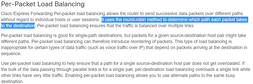
I have read this instruction. I read some terms, "Per Destination" and "Per Packet". In this instruction. It will be more useful to understand.

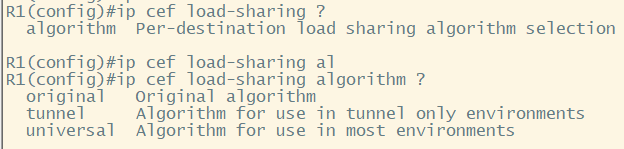
By this instruction, I can see the configuration paramter on interface like below.

For this verification, I will set up the GNS simulator like below. There are 3 links connected each other.

I will see the wireshark packet over each interface.
1. Per-Destination Algorithm
"Per-Desination" is default configuration. Therefore, it is now shown when I enter the CLI "ip load-sharing per-destination".

This algorithm is more similar with hashing method. The traffic will transfer over same interface. R1 has 3 loopback IP address, 1.1.1.1, 1.1.1.2 and 1.1.1.3. I will do ICMP with source. The traffic will use different links. However, It will be the same link when the source and destination are same.
[R1# ping 2.2.2.2 source 1.1.1.1 repeat 1]


R1 send ICMP request over Fa 2/1 and received over Fa 2/3.
[R1# ping 2.2.2.2 source 1.1.1.2 repeat 1]


R1 send ICMP request over Fa 2/2 and received over Fa 2/1.
[R1# ping 2.2.2.2 source 1.1.1.3 repeat 1]


R1 send ICMP request over Fa 2/2 and received over Fa 2/1.
Now I will do again in 10 minutes. It will be the same result.
[R1# ping 2.2.2.2 source 1.1.1.2 repeat 1]


R1 send ICMP request over Fa 2/2 and received over Fa 2/1.
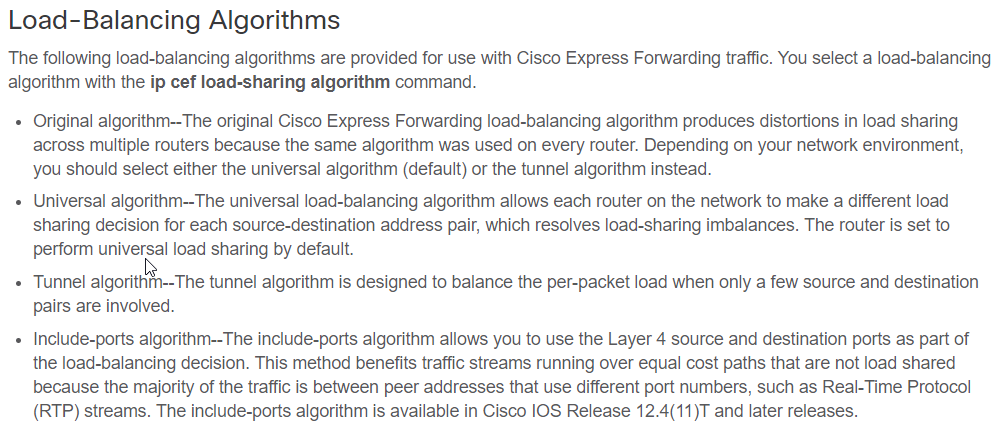
2. Select load-sharing algorithm for "Per-Destination"
This configuration give some option between R1 and R2. "Per-Destination" is the hashing algorithm. Thus R1 and R2 will show the same result. Because of this, some link can be intensive. For example, R1 --> Link 1 --> R2, R2 --> Link 1 --> R1 can be happend. Thus "Universal algorithm" make more dynmic distrubution on each switch with difference link.
3. Per Packet Algorithm.
I will configure like below on R1 and R2 switch.

After then, I will try to ping to R2. R2 has loopback IP address, 2.2.2.2/32.

I will get the result like below. This result show that the traffic are distributed by packet, even if it is single connection (source-destination IP address pair)
[FastEthernet 2/1]

[FastEthernet 2/2]

[FastEthernet 2/3]

Reference
[ 1 ] https://networkengineering.stackexchange.com/questions/27914/example-of-ecmp-uses-hashing-technique
'Network Engineering > Basic Learning' 카테고리의 다른 글
| How Can the Packet Size Be Greater than the MTU? (From other Post) (0) | 2020.09.02 |
|---|---|
| OSPFv2 BR/BDR, Unnumbered Interface(Network Area, IP OSPF Area) Simple Concept. (0) | 2020.06.05 |
| How does the OSPF cost work? (0) | 2019.07.18 |
| How to work BGP synchronize and next hop self with Nexus? (0) | 2019.07.11 |
| What is basic BGP community concept? (0) | 2019.06.18 |