How does the multicast (PIM sparse mode) work with MSDP? 


In this post, I will generate the multicast environment with Nx9000v on GNS3. I will handle the multicast with PIM sparse mode.


1. Pre-requiste for Test environments


I will produce this environment to generate the multicast.

Before I make Multicast environment, I need to prepare NAT for outbound traffic and Multicast test scripts. This is the sample configuration for NAT outbound traffic.

conf t

feature dhcp

feature nat

!

ip nat translation max-entries 1023

!

no ip dhcp relay

no ipv6 dhcp relay

!

inter eth 1/9

no sw

ip add dhcp

ip nat out

no shut

exit

inter et 1/7

no sw

ip add 100.15.5.17/16

ip nat ins

no shut

exit

inter et 1/8

no sw

ip add 100.25.5.18/16

ip nat ins

no shut

exit

!

ip acc 1

10 per ip any any

exit

!

ip nat inside source list 1 interface et1/9 overload

ip route 10.0.0.0/24 100.15.1.17

ip route 10.0.0.0/24 100.25.2.18

ip route 20.0.0.0/24 100.15.1.17

ip route 20.0.0.0/24 100.25.2.18

ip route 100.0.0.0/8 100.15.1.17

ip route 100.0.0.0/8 100.25.2.18

ip route 1.1.1.1/32 100.15.1.17

ip route 1.1.1.1/32 100.25.2.18

ip route 2.2.2.2/32 100.15.1.17

ip route 2.2.2.2/32 100.25.2.18

ip route 3.3.3.3/32 100.15.1.17

ip route 3.3.3.3/32 100.25.2.18

ip route 4.4.4.4/32 100.15.1.17

ip route 4.4.4.4/32 100.25.2.18

end

!

Also I attach the multicast example below

mcast-receiver.py
0.00MB
mcast-sender.py
0.00MB


2. Configuration for default environment.


2-1. Configure Core swtich/router  


I will make full-mesh connectivity. There are four switch/router. I will name as s1, s2, s3 and s4. On those switch/router, I will run OSPF routing to announce loopback addresses for Router ID and RP point. 

s1

s2

s3

s4

conf t
!
switchname s1
!
feature ospf
router ospf 1
router-id 1.1.1.1
exit
!
inter lo 0
ip add 1.1.1.1/32
ip router ospf 1 area 0.0.0.0
no shut
exit
!
inter et 1/7
no sw
ip add 100.15.1.17/16
no shut
exit
!
inter et 1/1
no sw
ip add 100.12.1.11/16
ip router ospf 1 area 0.0.0.0
no shut
exit
!
inter et 1/2
no sw
ip add 100.13.1.12/16
ip router ospf 1 area 0.0.0.0
no shut
exit
!
inter et 1/3
no sw
ip add 100.14.1.13/16
ip router ospf 1 area 0.0.0.0
no shut
exit
!
ip route 0.0.0.0/0 100.15.5.17
ip route 0.0.0.0/0 100.12.2.11 100
end
!

conf t
!
switchname s2
!
feature ospf
router ospf 1
router-id 2.2.2.2
exit
!
inter lo 0
ip add 2.2.2.2/32
ip router ospf 1 area 0.0.0.0
no shut
exit
!
inter et 1/8
no sw
ip add 100.25.2.18/16
no shut
exit
!
inter et 1/1
no sw
ip add 100.12.2.11/16
ip router ospf 1 area 0.0.0.0
no shut
exit
!
inter et 1/2
no sw
ip add 100.24.2.12/16
ip router ospf 1 area 0.0.0.0
no shut
exit
!
inter et 1/3
no sw
ip add 100.23.2.13/16
ip router ospf 1 area 0.0.0.0
no shut
exit
!
ip route 0.0.0.0/0 100.25.5.18
ip route 0.0.0.0/0 100.12.1.11 100
end
!

conf t
!
switchname s3
!
feature ospf
router ospf 1
router-id 3.3.3.3
exit
!
inter lo 0
ip add 3.3.3.3/32
ip router ospf 1 area 0.0.0.0
no shut
exit
!
inter et 1/1
no sw
ip add 100.34.3.11/16
ip router ospf 1 area 0.0.0.0
no shut
exit
!
inter et 1/2
no sw
ip add 100.13.3.12/16
ip router ospf 1 area 0.0.0.0
no shut
exit
!
inter et 1/3
no sw
ip add 100.23.3.13/16
ip router ospf 1 area 0.0.0.0
no shut
exit
!
ip route 0.0.0.0/0 1.1.1.1
ip route 0.0.0.0/0 2.2.2.2
!
vlan 10
name vlan10
exit
!
feature interface-vlan
inter vlan10
no shut
ip add 10.0.0.1/24
exit
!
inter et 1/7, et 1/8
sw mode ac
sw ac vlan 10
no shut
exit
!

----------------------------------
!
conf t
!
inter vlan 10
ip router ospf 1 area 0.0.0.0
exit
!
---------------------------------- 
conf t
!
feature pim
!
ip pim rp-address 99.99.99.99
!
inter eth 1/1, eth 1/2, eth 1/3
ip pim sparse-mode
exit
!
inter vlan 10
ip pim sparse-mode
exit
!

conf t
!
switchname s4
!
feature ospf
router ospf 1
router-id 4.4.4.4
exit
!
inter lo 0
ip add 4.4.4.4/32
ip router ospf 1 area 0.0.0.0
no shut
exit
!
inter et 1/1
no sw
ip add 100.34.4.11/16
ip router ospf 1 area 0.0.0.0
no shut
exit
!
inter et 1/2
no sw
ip add 100.24.4.12/16
ip router ospf 1 area 0.0.0.0
no shut
exit
!
inter et 1/3
no sw
ip add 100.14.4.13/16
ip router ospf 1 area 0.0.0.0
no shut
exit
!
ip route 0.0.0.0/0 1.1.1.1
ip route 0.0.0.0/0 2.2.2.2
!
vlan 20
name vlan20
exit
!
feature interface-vlan
inter vlan20
no shut
ip add 20.0.0.1/24
exit
!
inter et 1/7
sw mode ac
sw ac vlan 20
no shut
exit
!

----------------------------------
!
conf t
!
inter vlan 20
ip router ospf 1 area 0.0.0.0
exit
!
---------------------------------- 
conf t
!
feature pim
!
ip pim rp-address 99.99.99.99
!
inter eth 1/1, eth 1/2, eth 1/3
ip pim sparse-mode
exit
!
inter vlan 20
ip pim sparse-mode
exit
!

In s1 and s2, there are 2 kinds of loopback addresses. One is for the switch/router ID, the other is for the RP address. For loopback address for RP, I will utilize "ghost loopback address" method. Please look at the loopback interface 1 in s1 and s2.

s1 s2

conf t
!
feature pim
!
inter lo 1
ip address 99.99.99.99/32
ip router ospf 1 area 0.0.0.0
ip ospf network point
ip pim sparse-mode
no shutdown
exit
!
ip pim rp-address 99.99.99.99
!
inter eth 1/1, eth 1/2, eth 1/3
ip pim sparse-mode
exit
!

conf t
!
feature pim
!
inter lo 1
ip address 99.99.99.99/24
ip router ospf 1 area 0.0.0.0
ip ospf network point
ip pim sparse-mode
no shutdown
exit
!
ip pim rp-address 99.99.99.99
!
inter eth 1/1, eth 1/2, eth 1/3
ip pim sparse-mode
exit
!

S1 is the main RP server in normal status. However, it will be changed to s2 when S1 is failed without IP address change. Because of this, I need MSDP (Multicast Source Discovery Protocol). I will handle in later. To announce the network with subnet of loopback interface into OSPF, "Point to Point" is necesary. Now I can see the routing table on S3 and S4 switch/router.

s3# show ip route ospf-1 s4# show ip route ospf-1

1.1.1.1/32, ubest/mbest: 1/0
    *via 100.13.1.12, Eth1/2, [110/41], 3d00h, ospf-1, intra
2.2.2.2/32, ubest/mbest: 1/0
    *via 100.23.2.13, Eth1/3, [110/41], 3d00h, ospf-1, intra
4.4.4.4/32, ubest/mbest: 1/0
    *via 100.34.4.11, Eth1/1, [110/41], 3d00h, ospf-1, intra
20.0.0.0/24, ubest/mbest: 1/0
    *via 100.34.4.11, Eth1/1, [110/80], 03:33:46, ospf-1, intra
99.99.99.0/24, ubest/mbest: 1/0
    *via 100.23.2.13, Eth1/3, [110/41], 00:44:41, ospf-1, intra
99.99.99.99/32, ubest/mbest: 1/0
    *via 100.13.1.12, Eth1/2, [110/41], 00:44:41, ospf-1, intra
100.12.0.0/16, ubest/mbest: 2/0
    *via 100.13.1.12, Eth1/2, [110/80], 3d00h, ospf-1, intra
    *via 100.23.2.13, Eth1/3, [110/80], 3d00h, ospf-1, intra
100.14.0.0/16, ubest/mbest: 2/0
    *via 100.13.1.12, Eth1/2, [110/80], 3d00h, ospf-1, intra
    *via 100.34.4.11, Eth1/1, [110/80], 3d00h, ospf-1, intra
100.24.0.0/16, ubest/mbest: 2/0
    *via 100.23.2.13, Eth1/3, [110/80], 3d00h, ospf-1, intra
    *via 100.34.4.11, Eth1/1, [110/80], 3d00h, ospf-1, intra

1.1.1.1/32, ubest/mbest: 1/0
    *via 100.14.1.13, Eth1/3, [110/41], 3d00h, ospf-1, intra
2.2.2.2/32, ubest/mbest: 1/0
    *via 100.24.2.12, Eth1/2, [110/41], 3d00h, ospf-1, intra
3.3.3.3/32, ubest/mbest: 1/0
    *via 100.34.3.11, Eth1/1, [110/41], 3d00h, ospf-1, intra
10.0.0.0/24, ubest/mbest: 1/0
    *via 100.34.3.11, Eth1/1, [110/80], 03:34:26, ospf-1, intra
99.99.99.0/24, ubest/mbest: 1/0
    *via 100.24.2.12, Eth1/2, [110/41], 00:45:13, ospf-1, intra
99.99.99.99/32, ubest/mbest: 1/0
    *via 100.14.1.13, Eth1/3, [110/41], 00:45:13, ospf-1, intra
100.12.0.0/16, ubest/mbest: 2/0
    *via 100.14.1.13, Eth1/3, [110/80], 3d00h, ospf-1, intra
    *via 100.24.2.12, Eth1/2, [110/80], 3d00h, ospf-1, intra
100.13.0.0/16, ubest/mbest: 2/0
    *via 100.14.1.13, Eth1/3, [110/80], 3d00h, ospf-1, intra
    *via 100.34.3.11, Eth1/1, [110/80], 3d00h, ospf-1, intra
100.23.0.0/16, ubest/mbest: 2/0
    *via 100.24.2.12, Eth1/2, [110/80], 3d00h, ospf-1, intra
    *via 100.34.3.11, Eth1/1, [110/80], 3d00h, ospf-1, intra

In red text above, "100.100.100.100" is the RP address for multicast. At this time, the destination should be s1. It will be changed to s2 by "100.100.100.0/24", when s1 is failed.


2-2. Configure the Host (PC, Labtop) network.


s3 and s4 is the gateway for each host network. In my scenario, I will use "10.0.0.0/24" for PC1 and "20.0.0.0/24" for PC2.

I have already done for the gateway above.

S3

S4

!

conf t

!

inter vlan 10

ip router ospf 1 area 0.0.0.0

exit

!

inter eth 1/1, eth 1/2, eth 1/3

ip pim sparse-mode

exit

!

inter vlan 10

ip pim sparse-mode

exit

!

!

conf t

!

inter vlan 20

ip router ospf 1 area 0.0.0.0

exit

!

inter eth 1/1, eth 1/2, eth 1/3

ip pim sparse-mode

exit

!

inter vlan 20

ip pim sparse-mode

exit

!

Now I will configure the PC network interface. In my case I will use "Ubuntu Desktop". In this instruction, I can see how to install "ubuntu" in GNS3. After installation, I can open the console like below.

After login, I can set the network interface like below. I need to update file in "/etc/network/interfaces".

After set both of hosts, I can send ICMP packet each other.


However, there is one more thing necessary. To Join and receive the multicast packet. I need to define the IGMP version on Linux host sometimes. This instruction will be helpful.

echo "2" >> /proc/sys/net/ipv4/conf/<interface>/force_igmp_version

In my case, Host 2 and Host 3 will be receiver, therefore it will be like below


3. Configuraton for Multicast environment.


3-1. Configure for default multicast 


In fact, I have already done for multicast routing, if you follow sample configuration. This instruction will be helpful to understand how to configure.

S1 S2 S3 S4

conf t

!

feature pim

!

inter lo 1

ip address 99.99.99.99/32

ip router ospf 1 area 0.0.0.0

ip ospf network point

ip pim sparse-mode

no shutdown

exit

!

ip pim rp-address 99.99.99.99

!

inter eth 1/1, eth 1/2, eth 1/3

ip pim sparse-mode

exit

!

conf t

!

feature pim

!

inter lo 1

ip address 99.99.99.99/24

ip router ospf 1 area 0.0.0.0

ip ospf network point

ip pim sparse-mode

no shutdown

exit

!

ip pim rp-address 99.99.99.99

!

inter eth 1/1, eth 1/2, eth 1/3

ip pim sparse-mode

exit

!

conf t

!

feature pim

!

ip pim rp-address 99.99.99.99

!

inter eth 1/1, eth 1/2, eth 1/3

ip pim sparse-mode

exit

!

inter vlan 10

ip pim sparse-mode

exit

!

conf t

!

feature pim

!

ip pim rp-address 99.99.99.99

!

inter eth 1/1, eth 1/2, eth 1/3

ip pim sparse-mode

exit

!

inter vlan 20

ip pim sparse-mode

exit

!

Now, I can test multicast routing with sample script. I can get the result like below.

I success to send multicast traffic. However, I still leave MSDP. "99.99.99.99" is the RP which is S1. I worry the S1 fail situation. MSDP is one of good solution. Please read next step.


3-2. Configure for MSDP.


Before, I configure for MSDP. Any information was not shared each other. (S1 and S2 are peer connection for MSDP). I run command "show ip msdp route" and "show ip msdp sa-cache".

Because of this, the routing information should be registered again on S2, when S1 is failed. Now, I will follow this instruction. At first, I will MSDP configuration to share source information between s1 and s2.

In above, there is "ip msdp cache-sa-state" command for caching. However, there is no command in Nx9000v in my case. Therefore, my configuration should be below.

s1 s2

feature msdp

ip msdp originator-id loopback0

ip msdp peer 1.1.1.2 connect-source loopback0

feature msdp

ip msdp originator-id loopback0

ip msdp peer 1.1.1.1 connect-source loopback0

I can check the status with "show ip msdp summary

I can also verify the status with again "show ip msdp route" and "show ip msdp sa-cache".

In fact, I can not understand this effect.


3-3. Verify the MSDP effect.


Before MSDP configuration, I will shutodown loopback 1 (RP) of S1 switch/router. In S2 switch/router, there is no multicast source information.

After sender request, the source information is updated. This is normal case

Now, I will configure MSDP. I will shutdown loopback 1 of switch/router S1 again. In S2,

Multicast routing information is updated directly.


Sample Configurations

S1
0.00MB
S2
0.00MB
S3
0.00MB
S4
0.00MB
S5
0.00MB


Reference


[ 1 ] https://www.osboxes.org/ubuntu/#ubuntu-14_04-vmware

[ 2 ] https://docs.gns3.com/1RpM21DdgL2pCNtIrw6e9Yf52tRjYZIe46LMeESl-jy4/

[ 3 ] https://www.cisco.com/c/en/us/td/docs/ios/12_2/ip/configuration/guide/fipr_c/1cfmsdp.html#wp1000963

[ 4 ] https://createnetech.tistory.com/40?category=672584

[ 5 ] https://pymotw.com/2/socket/multicast.html

[ 6 ] https://sites.google.com/site/miclinuxcorner/technology/multicast-routing

[ 7 ] https://www.cisco.com/c/en/us/support/docs/ip/ip-multicast/9356-48.html#msdp

In this post, I will install the kubernetes with external etcd. Most of instrcution come from here. I will follow step by step as the beginner.


kubeadm-init.yaml
0.00MB


1. Pre-requsite


At first I need to prepare the hosts for Kubernetes components. In my case, I have 5 nodes, one for master, one for external etcd and three for workers. After I prepare these nodes. I need to update "/etc/hostname" and "/etc/hosts" files propertly. For example, I have to change hostname to "m1" as master node.

# hostname m1

# vi /etc/hostname
m1

# vi /etc/hosts
127.0.0.1       localhost       m1
147.75.94.251 m1
147.75.92.69 e1
147.75.92.139 w1
147.75.92.71 w2

After this, I need to log-out and log-in again.

Kubernetes use Docker engine. Therefore, I need to install Docker. I will follow this instruction. In my case, I will run this kubernetes over Ubuntu 16.04. This is overview.

sudo apt-get update
sudo apt-get install -y \
    apt-transport-https \
    ca-certificates \
    curl \
    gnupg-agent \
    software-properties-common

curl -fsSL https://download.docker.com/linux/ubuntu/gpg | sudo apt-key add -
sudo apt-key fingerprint 0EBFCD88
sudo add-apt-repository \
   "deb [arch=amd64] https://download.docker.com/linux/ubuntu \
   $(lsb_release -cs) \
   stable"
sudo apt-get update
sudo apt-get install -y docker-ce docker-ce-cli containerd.io

I need to check docker info. It will be like below. I need to check "Cgroup Driver: cgroupfs" as default.

# docker info
Server Version: 18.09.6
Storage Driver: overlay2
 Backing Filesystem: extfs
 Supports d_type: true
 Native Overlay Diff: true
Logging Driver: json-file
Cgroup Driver: cgroupfs
Plugins:
 Volume: local
 Network: bridge host macvlan null overlay
 Log: awslogs fluentd gcplogs gelf journald json-file local logentries splunk syslog
Swarm: inactive

From this instruction, I will change this driver from "cgroupsfs" to "systemd". This change affect lots of issue during Kubernetes installation. Therefore I need to remember this.

cat > /etc/docker/daemon.json <{
  "exec-opts": ["native.cgroupdriver=systemd"],
  "log-driver": "json-file",
  "log-opts": {
    "max-size": "100m"
  },
  "storage-driver": "overlay2"
}
EOF
mkdir -p /etc/systemd/system/docker.service.d
systemctl daemon-reload
systemctl restart docker

After this, Cgroup Driver will be changed 

# docker info
Cgroup Driver: systemd


2. Install kubelet, kubeadm and kubectl


Kubelet (daemon on each node has the role to handle conatiner), kubeadm (daemon on each node has the role to setup master and workers) and kubectl (daemon on each node has the role to manage the cluster) are necessary components.

apt-get update && apt-get install -y apt-transport-https curl
curl -s https://packages.cloud.google.com/apt/doc/apt-key.gpg | apt-key add -
cat </etc/apt/sources.list.d/kubernetes.list
deb https://apt.kubernetes.io/ kubernetes-xenial main
EOF
apt-get update
apt-get install -y kubelet kubeadm kubectl
apt-mark hold kubelet kubeadm kubectl

After installation, I need to check the directories which are created during the installation. "/etc/kubernetes/" and "/var/lib/kubelet/pki/" and "/etc/systemd/system/kubelet.service.d/" are created. 

# ls /etc/kubernetes/ 
manifests 
# ls /etc/kubernetes/manifests/ 
# ls /var/lib/kubelet/ 
pki 
# ls /var/lib/kubelet/pki/ 
kubelet.crt  kubelet.key 
# ls /etc/systemd/system/kubelet.service.d/
10-kubeadm.conf 

To work Kubernetes normally, Kubelet work normally at first. I can check the status with "systemctl status kubelet". At this moment, it is not activate.

# systemctl status kubelet

  kubelet.service - kubelet: The Kubernetes Node Agent

   Loaded: loaded (/lib/systemd/system/kubelet.service; enabled; vendor preset: enabled)

  Drop-In: /etc/systemd/system/kubelet.service.d

           └─10-kubeadm.conf

   Active: activating (auto-restart) (Result: exit-code) since Wed 2019-05-22 10:59:59 UTC; 2s ago

     Docs: https://kubernetes.io/docs/home/

  Process: 12883 ExecStart=/usr/bin/kubelet $KUBELET_KUBECONFIG_ARGS $KUBELET_CONFIG_ARGS $KUBELET_KUBEADM_ARGS $KUBELET_EXTRA_ARGS (code=

 Main PID: 12883 (code=exited, status=255)

May 22 10:59:59 e1 systemd[1]: kubelet.service: Main process exited, code=exited, status=255/n/a

May 22 10:59:59 e1 systemd[1]: kubelet.service: Unit entered failed state.

May 22 10:59:59 e1 systemd[1]: kubelet.service: Failed with result 'exit-code'.

To see more details, I will look at the logs in "/var/log/syslog". From logs, I can check I need "config.yaml" file. Keep this issue and go to next step. This file will be created with "kubectl init" command later.

# tail -f /var/log/syslog

systemd[1]: kubelet.service: Service hold-off time over, scheduling restart.

systemd[1]: Stopped kubelet: The Kubernetes Node Agent.

systemd[1]: Started kubelet: The Kubernetes Node Agent.

kubelet[12865]: F0522 10:59:49.732907   12865 server.go:193] failed to load Kubelet config file /var/lib/kubelet/config.yaml, error failed to read kubelet config file "/var/lib/kubelet/config.yaml", error: open /var/lib/kubelet/config.yaml: no such file or directory

systemd[1]: kubelet.service: Main process exited, code=exited, status=255/n/a

systemd[1]: kubelet.service: Unit entered failed state.

systemd[1]: kubelet.service: Failed with result 'exit-code'.

I need to match the cgroup driver with the value "systemd". In the instruction, there is the comment like below.

However there are no "/etc/default/kubelet" and "/var/lib/kubelet/kubeadm-flags.env". So I can not update this with this instruction. Please look at the result from "systemctl status kubelet". I can see "/etc/systemd/system/kubelet.service.d/10-kubeadm.conf". This is the loaded file when kubelet is started.

# Note: This dropin only works with kubeadm and kubelet v1.11+

[Service]

Environment="KUBELET_KUBECONFIG_ARGS=--bootstrap-kubeconfig=/etc/kubernetes/bootstrap-kubelet.conf --kubeconfig=/etc/kubernetes/kubelet.conf"

Environment="KUBELET_CONFIG_ARGS=--config=/var/lib/kubelet/config.yaml"

Environment="KUBELET_EXTRA_ARGS=--cgroup-driver=systemd"

# This is a file that "kubeadm init" and "kubeadm join" generates at runtime, populating the KUBELET_KUBEADM_ARGS variable dynamically

EnvironmentFile=-/var/lib/kubelet/kubeadm-flags.env

# This is a file that the user can use for overrides of the kubelet args as a last resort. Preferably, the user should use

# the .NodeRegistration.KubeletExtraArgs object in the configuration files instead. KUBELET_EXTRA_ARGS should be sourced from this file.

EnvironmentFile=-/etc/default/kubelet

ExecStart=

ExecStart=/usr/bin/kubelet $KUBELET_KUBECONFIG_ARGS $KUBELET_CONFIG_ARGS $KUBELET_KUBEADM_ARGS $KUBELET_EXTRA_ARGS

I will add the red text, Environment="KUBELET_EXTRA_ARGS=--cgroup-driver=systemd". And restart the kubelet with "systemctl daemon-reload" and "systemctl restart kubelet". However, it is still not activated due to no config.yaml.


3. Install external etcd cluster


I have alread posted in here. To create the etcd cluster, It is not easy. However, I can make these with this instruction easliy. This etcd will be created as one of container application which are managed by Kubernetes. On the external etcd node, I have to run command below.

cat << EOF > /etc/systemd/system/kubelet.service.d/20-etcd-service-manager.conf 

[Service] 

ExecStart= 

ExecStart=/usr/bin/kubelet --address=127.0.0.1 --pod-manifest-path=/etc/kubernetes/manifests --allow-privileged=true 

Restart=always 

EOF

systemctl daemon-reload

systemctl restart kubelet

 Please note that there is no option for cgroup drivers. Therefore, I need to change something.

Environment="KUBELET_EXTRA_ARGS=--cgroup-driver=systemd"
ExecStart=
ExecStart=/usr/bin/kubelet --address=0.0.0.0 --pod-manifest-path=/etc/kubernetes/manifests --allow-privileged=true $KUBELET_EXTRA_ARGS
Restart=always

The file name start with 20-etcd-service-manager.conf due to "20", so it has higher priority rather than 10-kubeadm.conf. After running this, I can check the "systemctl status kubelet" and "/var/log/syslog". The kubelet does not works with some error. This error is different from above. The first error above is happend after 10-kubeadm.conf loading. However this error is happend during 20-etcd-service-manager.conf loading. So I have to solve this error at first.

tail -f /var/log/syslog

systemd[1]: kubelet.service: Service hold-off time over, scheduling restart.

systemd[1]: Stopped kubelet: The Kubernetes Node Agent.

systemd[1]: Started kubelet: The Kubernetes Node Agent.

kubelet[28517]: Flag --address has been deprecated, This parameter should be set via the config file specified by the Kubelet's --config flag. See https://kubernetes.io/docs/tasks/administer-cluster/kubelet-config-file/ for more information.

kubelet[28517]: Flag --pod-manifest-path has been deprecated, This parameter should be set via the config file specified by the Kubelet's --config flag. See https://kubernetes.io/docs/tasks/administer-cluster/kubelet-config-file/ for more information.

kubelet[28517]: Flag --allow-privileged has been deprecated, will be removed in a future version

kubelet[28517]: Flag --cgroup-driver has been deprecated, This parameter should be set via the config file specified by the Kubelet's --config flag. See https://kubernetes.io/docs/tasks/administer-cluster/kubelet-config-file/ for more information.

systemd[1]: Started Kubernetes systemd probe.

kubelet[28517]: I0522 14:05:31.497808   28517 server.go:417] Version: v1.14.2

kubelet[28517]: I0522 14:05:31.498194   28517 plugins.go:103] No cloud provider specified.

kubelet[28517]: W0522 14:05:31.498229   28517 server.go:556] standalone mode, no API client

kubelet[28517]: W0522 14:05:31.598549   28517 server.go:474] No api server defined - no events will be sent to API server.

kubelet[28517]: I0522 14:05:31.598601   28517 server.go:625] --cgroups-per-qos enabled, but --cgroup-root was not specified.  defaulting to /

kubelet[28517]: F0522 14:05:31.599231   28517 server.go:265] failed to run Kubelet: Running with swap on is not supported, please disable swap! or set --fail-swap-on flag to false. /proc/swaps contained: [Filename#011#011#011#011Type#011#011Size#011Used#011Priority /dev/sda2  partition#0111996796#0110#011-1]

systemd[1]: kubelet.service: Main process exited, code=exited, status=255/n/a

systemd[1]: kubelet.service: Unit entered failed state.

systemd[1]: kubelet.service: Failed with result 'exit-code'.

There are some error and warning messages. To solve this, I have to create "kubeadmcfg.yaml" from this instruction. In my case, I will difference file name like below

# cat external-etcd-cfg.yaml
apiVersion: "kubeadm.k8s.io/v1beta1"
kind: ClusterConfiguration
controlPlaneEndpoint: 147.75.94.251:6443
etcd:
    local:
        serverCertSANs:
        - "147.75.92.69"
        peerCertSANs:
        - "147.75.92.69"
        extraArgs:
            initial-cluster: e1=https://147.75.92.69:2380
            initial-cluster-state: new
            name: e1
            listen-peer-urls: https://147.75.92.69:2380
            listen-client-urls: https://147.75.92.69:2379
            advertise-client-urls: https://147.75.92.69:2379
            initial-advertise-peer-urls: https://147.75.92.69:2380

"controlPlaneEndpoint: 147.75.94.251:6443" is master IP address and Port for API server. This parameter solve this warning "No api server defined - no events will be sent to API server.". 147.75.92.69 ip address is external etcd node interface IP addresss which is announced for outside. In this yaml file, some options are included. Therefore, I have to revise 20-etcd-service-manager.conf file like below. 

Even if I added more options in yaml file, I do not handle root cause why the kubelet fail. In the syslog, "failed to run Kubelet: Running with swap on is not supported, please disable swap! or set --fail-swap-on flag to false" is the main reason. To solve this, there are 3 option.

# swapoff -a

# vi /etc/fstab

UUID=b7edcf12-2397-489a-bed1-4b5a3c4b1df3       /       ext4    errors=remount-ro       0       1

# UUID=a3babb9d-5aee-4a1d-a894-02aa816ef6e7       none    swap    none    0       0

"swapoff -a" is temporary option. Comment "swap" in "/etc/fstab" is permenant option. Adding " --fail-swap-on=false" in 20-etcd-service-manager.conf is another permenant option. After then, the status of kubelet will be like this.

Environment="KUBELET_EXTRA_ARGS=--cgroup-driver=systemd" 
ExecStart= 
ExecStart=/usr/bin/kubelet --address=0.0.0.0 --pod-manifest-path=/etc/kubernetes/manifests --allow-privileged=true --fail-swap-on=false $KUBELET_EXTRA_ARGS 
Restart=always

Now, I am ready to deploy etcd container deployment. I need certificate and private key for etcd cluster to work well. These values are located in "/etc/kubernetes/pki/etcd". However, you do not have this directory at this time. As the instruction, these file will be generated with command below.

# kubeadm init phase certs etcd-ca
[certs] Generating "etcd/ca" certificate and key
# ls /etc/kubernetes/pki/etcd/
ca.crt  ca.key

If you are want to make cluster of etcd nodes, I have copy these files on each etcd nodes. However, it is not enough to work well. I need more certiface and key.

kubeadm init phase certs etcd-server --config=external-etcd-cfg.yaml

kubeadm init phase certs etcd-peer --config=external-etcd-cfg.yaml

kubeadm init phase certs etcd-healthcheck-client --config=external-etcd-cfg.yaml

kubeadm init phase certs apiserver-etcd-client --config=external-etcd-cfg.yaml

after then, serveral key will be generated. In fact, some of key is not necessary if you run single external etcd node. Now, I can run etcd container with command below

# kubeadm init phase etcd local --config=external-etcd-cfg.yaml

# docker ps
CONTAINER ID        IMAGE                  COMMAND                  CREATED             STATUS              PORTS               NAMES
f7f427f30a04        2c4adeb21b4f           "etcd --advertise-cl…"   16 minutes ago      Up 16 minutes                           k8s_etcd_etcd-e1_kube-system_9a37a797efa5968588eac7b51458eecc_0
5686bb62b14f        k8s.gcr.io/pause:3.1   "/pause"                 16 minutes ago      Up 16 minutes                           k8s_POD_etcd-e1_kube-system_9a37a797efa5968588eac7b51458eecc_0


# docker exec f7f427f30a04 etcdctl --cert-file /etc/kubernetes/pki/etcd/peer.crt --key-file /etc/kubernetes/pki/etcd/peer.key --ca-file /etc/kubernetes/pki/etcd/ca.crt --endpoints https://147.75.92.69:2379 cluster-health
member d3b00bc687dc09ae is healthy: got healthy result from https://147.75.92.69:2379
cluster is healthy

I can also check the health status.


4. Install master nodes


There are 2 instructions for master node, single master and cluser masters. To setup the master node, I need configuration file. I will refer from this instruction. This is the sample configuration yaml file what I have

cat < ./kubeadm-config.yaml

apiVersion: kubeadm.k8s.io/v1beta1

kind: InitConfiguration

localAPIEndpoint:

  advertiseAddress: 147.75.94.251

  bindPort: 6443

---

apiVersion: kubeadm.k8s.io/v1beta1

kind: ClusterConfiguration

kubernetesVersion: v1.14.1

clusterName: crenet-cluster

controlPlaneEndpoint: 147.75.94.251:6443

networking:

  podSubnet: 10.244.0.0/16

controllerManager:

  extraArgs:

    deployment-controller-sync-period: "50s"

---
apiVersion: kubeproxy.config.k8s.io/v1alpha1
kind: KubeProxyConfiguration
mode: ipvs

EOF

With this configuration above, I can run "kubeadm init". Please note that "mode: ipvs" will change the kube-proxy mode to work with "ipvsadm" kerneal module. In the post what I wrote, It will be undertand how kube-proxy work with this part. This is overview to install and load kernal module

apt-get install ipvsadm
echo "net.ipv4.conf.all.arp_ignore=1" >> /etc/sysctl.conf
echo "net.ipv4.conf.all.arp_announce=2" >> /etc/sysctl.conf
sysctl -p /etc/sysctl.conf

modprobe ip_vs_rr  
modprobe ip_vs_wrr  
modprobe ip_vs_sh 
modprobe ip_vs

Sometimes, some module are not loaded. So I need to do manually with "modeprobe". If these module are not loaed when kubeadm init is started, I can see this message "kernel modules are not loaded: [ip_vs ip_vs_rr ip_vs_wrr ip_vs_sh]

Now, it will load the file "/etc/systemd/system/kubelet.service.d/10-kubeadm.conf".

# cat /etc/systemd//system/kubelet.service.d/10-kubeadm.conf

# Note: This dropin only works with kubeadm and kubelet v1.11+

[Service]

Environment="KUBELET_KUBECONFIG_ARGS=--bootstrap-kubeconfig=/etc/kubernetes/bootstrap-kubelet.conf --kubeconfig=/etc/kubernetes/kubelet.conf"

Environment="KUBELET_CONFIG_ARGS=--config=/var/lib/kubelet/config.yaml"

Environment="KUBELET_EXTRA_ARGS=--cgroup-driver=systemd"

# This is a file that "kubeadm init" and "kubeadm join" generates at runtime, populating the KUBELET_KUBEADM_ARGS variable dynamically

EnvironmentFile=-/var/lib/kubelet/kubeadm-flags.env

# This is a file that the user can use for overrides of the kubelet args as a last resort. Preferably, the user should use

# the .NodeRegistration.KubeletExtraArgs object in the configuration files instead. KUBELET_EXTRA_ARGS should be sourced from this file.

EnvironmentFile=-/etc/default/kubelet

ExecStart=

ExecStart=/usr/bin/kubelet $KUBELET_KUBECONFIG_ARGS $KUBELET_CONFIG_ARGS $KUBELET_KUBEADM_ARGS $KUBELET_EXTRA_ARGS

With this configuration I can run "kubeadm init" 

swapoff -a

sudo kubeadm init --config=kubeadm-config.yaml --experimental-upload-certs

before run kubeadm init, I need to "swapoff -a". I can get some error message without "swapoff -a"

[init] Using Kubernetes version: v1.14.1

[preflight] Running pre-flight checks

error execution phase preflight: [preflight] Some fatal errors occurred:

        [ERROR Swap]: running with swap on is not supported. Please disable swap

[preflight] If you know what you are doing, you can make a check non-fatal with `--ignore-preflight-errors=...`

Anyway, I will get this result when I make master node succefully.

Your Kubernetes control-plane has initialized successfully!

To start using your cluster, you need to run the following as a regular user:

  mkdir -p $HOME/.kube

  sudo cp -i /etc/kubernetes/admin.conf $HOME/.kube/config

  sudo chown $(id -u):$(id -g) $HOME/.kube/config

You should now deploy a pod network to the cluster.

Run "kubectl apply -f [podnetwork].yaml" with one of the options listed at:

  https://kubernetes.io/docs/concepts/cluster-administration/addons/

You can now join any number of the control-plane node running the following command on each as root:

  kubeadm join 147.75.94.251:6443 --token 9nbo8n.y8oke84pmjgaj3px \

    --discovery-token-ca-cert-hash sha256:ac3693f08617ad045bf2e18a1ec0c3240e0651057dcd29e52daa21176a02b9f6 \

    --experimental-control-plane --certificate-key 1eae6218e326a045b866b38e4c0b0135d49203073bfe4f06f602e415dcd9b7a6

Please note that the certificate-key gives access to cluster sensitive data, keep it secret!

As a safeguard, uploaded-certs will be deleted in two hours; If necessary, you can use

"kubeadm init phase upload-certs --experimental-upload-certs" to reload certs afterward.

Then you can join any number of worker nodes by running the following on each as root:

kubeadm join 147.75.94.251:6443 --token 9nbo8n.y8oke84pmjgaj3px \

    --discovery-token-ca-cert-hash sha256:ac3693f08617ad045bf2e18a1ec0c3240e0651057dcd29e52daa21176a02b9f6

I need more steps. First I configure for "kubectl" enable.

mkdir -p $HOME/.kube

sudo cp -i /etc/kubernetes/admin.conf $HOME/.kube/config

sudo chown $(id -u):$(id -g) $HOME/.kube/config

After this, I can use "kubectl" command. Sometimes, master status can be "NotReady". At this time, I should check the status of pods with "kubectl get pods --all-namespace"

# kubectl get nodes

NAME   STATUS     ROLES    AGE     VERSION

m1     NotReady   master   4m43s   v1.14.2


From this instruction, I need to POD network to solve this issue.

To install POD network, look at this instuction.

In my case, I will use "Flannel".

echo "net.bridge.bridge-nf-call-iptables=1" >> /etc/sysctl.conf
sysctl -p /etc/sysctl.conf
wget https://raw.githubusercontent.com/coreos/flannel/62e44c867a2846fefb68bd5f178daf4da3095ccb/Documentation/kube-flannel.yml
kubectl apply -f kube-flannel.yml

And then, the master status is normal

# kubectl get pods --all-namespaces

NAMESPACE     NAME                          READY   STATUS    RESTARTS   AGE

kube-system   coredns-fb8b8dccf-627rr       1/1     Running   0          16m

kube-system   coredns-fb8b8dccf-kwvb4       1/1     Running   0          16m

kube-system   etcd-m1                       1/1     Running   0          15m

kube-system   kube-apiserver-m1             1/1     Running   0          15m

kube-system   kube-controller-manager-m1    1/1     Running   0          15m

kube-system   kube-flannel-ds-amd64-6s7xh   1/1     Running   0          54s

kube-system   kube-proxy-gm6bl              1/1     Running   0          16m

kube-system   kube-scheduler-m1             1/1     Running   0          15m


# kubectl get nodes

NAME   STATUS   ROLES    AGE   VERSION

m1     Ready    master   17m   v1.14.2

Oh It is work now. See status with more information

# systemctl status kubelet
  kubelet.service - kubelet: The Kubernetes Node Agent
   Loaded: loaded (/lib/systemd/system/kubelet.service; enabled; vendor preset: enabled)
  Drop-In: /etc/systemd/system/kubelet.service.d
           └─10-kubeadm.conf
   Active: active (running) since Wed 2019-05-22 15:44:37 UTC; 1h 29min ago
     Docs: https://kubernetes.io/docs/home/
 Main PID: 1490 (kubelet)
    Tasks: 21
   Memory: 35.9M
      CPU: 4min 37.546s
   CGroup: /system.slice/kubelet.service
           └─1490 /usr/bin/kubelet --fail-swap-on=false --bootstrap-kubeconfig=/etc/kubernetes/bootstrap-kubelet.conf --kubeconfig=/etc/kubernetes/kubelet.conf --config=/var/lib

# cat /var/lib/kubelet/config.yaml | grep -i cgroup
cgroupDriver: cgroupfs
cgroupsPerQOS: true

There is something strange. "cgroupDriver: cgroupfs" is strange. It should be "systemd", becuase I update "Environment="KUBELET_EXTRA_ARGS=--cgroup-driver=systemd" in "/etc/systemd/system/kubelet.service.d/10-kubeadm.conf". I think it is not work. I will update for this

# cat kubeadm-config.yaml

apiVersion: kubeadm.k8s.io/v1beta1

kind: InitConfiguration

localAPIEndpoint:

  advertiseAddress: 147.75.94.251

  bindPort: 6443

---

apiVersion: kubeadm.k8s.io/v1beta1

kind: ClusterConfiguration

kubernetesVersion: v1.14.1

clusterName: crenet-cluster

controlPlaneEndpoint: 147.75.94.251:6443

networking:

  podSubnet: 10.244.0.0/16

controllerManager:

  extraArgs:

    deployment-controller-sync-period: "50s"

---

apiVersion: kubelet.config.k8s.io/v1beta1

kind: KubeletConfiguration

cgroupDriver: systemd

------
apiVersion: kubeproxy.config.k8s.io/v1alpha1
kind: KubeProxyConfiguration
mode: ipvs

I will run "kubeadm reset" and "kubeadm init" again. Now

# cat /var/lib/kubelet/config.yaml | grep -i cgroup
cgroupDriver: systemd

However, this is not all of things. I have alread made external etcd. I have not configure for this yet. Default, etcd conatiner is located on each master node. They are not clustered.

# kubectl get pods --all-namespaces

NAMESPACE     NAME                          READY   STATUS    RESTARTS   AGE

kube-system   coredns-fb8b8dccf-627rr       1/1     Running   0          73m

kube-system   coredns-fb8b8dccf-kwvb4       1/1     Running   0          73m

kube-system   etcd-m1                       1/1     Running   0          72m

kube-system   kube-apiserver-m1             1/1     Running   0          72m

kube-system   kube-controller-manager-m1    1/1     Running   0          72m

kube-system   kube-flannel-ds-amd64-6s7xh   1/1     Running   0          57m

kube-system   kube-proxy-gm6bl              1/1     Running   0          73m

kube-system   kube-scheduler-m1             1/1     Running   0          72m

From this instruction, there are serveral step for this. At first I need to copy the certificate and key from etcd node.

Now, I need to update my configuration file

# cat kubeadm-config.yaml

apiVersion: kubeadm.k8s.io/v1beta1

kind: InitConfiguration

localAPIEndpoint:

  advertiseAddress: 147.75.94.251

  bindPort: 6443

---

apiVersion: kubeadm.k8s.io/v1beta1

kind: ClusterConfiguration

kubernetesVersion: v1.14.1

clusterName: crenet-cluster

controlPlaneEndpoint: 147.75.94.251:6443

networking:

  podSubnet: 10.244.0.0/16

controllerManager:

  extraArgs:

    deployment-controller-sync-period: "50s"

etcd:

    external:

        endpoints:

        - https://147.75.92.69:2379

        caFile: /etc/kubernetes/pki/etcd/ca.crt

        certFile: /etc/kubernetes/pki/apiserver-etcd-client.crt

        keyFile: /etc/kubernetes/pki/apiserver-etcd-client.key

---

apiVersion: kubelet.config.k8s.io/v1beta1

kind: KubeletConfiguration

cgroupDriver: systemd

---

---
apiVersion: kubeproxy.config.k8s.io/v1alpha1
kind: KubeProxyConfiguration
mode: ipvs

Now, I will run "kubeadm reset" and "kubeadm init" again. Please note that the certificate and key will be remove when I run kubeadm reset. Therefore, I need to copy again from etcd node

error execution phase preflight: [preflight] Some fatal errors occurred:
        [ERROR ExternalEtcdVersion]: couldn't load external etcd's server certificate /etc/kubernetes/pki/etcd/ca.crt: open /etc/kubernetes/pki/etcd/ca.crt: no such file or directory
        [ERROR ExternalEtcdClientCertificates]: /etc/kubernetes/pki/etcd/ca.crt doesn't exist
        [ERROR ExternalEtcdClientCertificates]: /etc/kubernetes/pki/apiserver-etcd-client.crt doesn't exist
        [ERROR ExternalEtcdClientCertificates]: /etc/kubernetes/pki/apiserver-etcd-client.key doesn't exist
[preflight] If you know what you are doing, you can make a check non-fatal with `--ignore-preflight-errors=...`

After I copy the certificate and key, I can check the status again

# kubectl get pods --all-namespaces

NAMESPACE     NAME                          READY   STATUS    RESTARTS   AGE

kube-system   coredns-fb8b8dccf-nzv2s       0/1     Running   0          2m30s

kube-system   coredns-fb8b8dccf-v74jz       0/1     Running   0          2m30s

kube-system   kube-apiserver-m1             1/1     Running   0          113s

kube-system   kube-controller-manager-m1    1/1     Running   0          92s

kube-system   kube-flannel-ds-amd64-6sqzv   1/1     Running   0          18s

kube-system   kube-proxy-s6sj7              1/1     Running   0          2m29s

kube-system   kube-scheduler-m1             1/1     Running   0          94s

etcd is not existed on master node. 


5. Setup the Worker nodes


It is almost same. I need docker engin and kubeadm, kubectl, kubelet. I have already explain about these above. After creating master node, I can see the message like below

 kubeadm join 147.75.94.251:6443 --token 9nbo8n.y8oke84pmjgaj3px \

    --discovery-token-ca-cert-hash sha256:ac3693f08617ad045bf2e18a1ec0c3240e0651057dcd29e52daa21176a02b9f6 \

    --experimental-control-plane --certificate-key 1eae6218e326a045b866b38e4c0b0135d49203073bfe4f06f602e415dcd9b7a6


kubeadm join 147.75.94.251:6443 --token 9nbo8n.y8oke84pmjgaj3px \

    --discovery-token-ca-cert-hash sha256:ac3693f08617ad045bf2e18a1ec0c3240e0651057dcd29e52daa21176a02b9f6

First is for adding master node, second is for adding worker node. I need some information such as token.

# kubeadm token list

TOKEN                     TTL       EXPIRES                USAGES                   DESCRIPTION                                           EXTRA GROUPS

seiuxa.fsaa2107s0vl10kg   1h        2019-05-22T19:27:32Z                      Proxy for managing TTL for the kubeadm-certs secret   

yo0mwz.5mc41r1gn90akio2   23h       2019-05-23T17:27:33Z   authentication,signing                                                   system:bootstrappers:kubeadm:default-node-token


# openssl x509 -pubkey -in /etc/kubernetes/pki/ca.crt | openssl rsa -pubin -outform der 2>/dev/null | \

>    openssl dgst -sha256 -hex | sed 's/^.* //'

aeebcc777388b5ecde64801a51d2e37cf7ff2410e8e64f1832694fc3946d7c27

With these values, I can run command on each worker node. I will check the status of the cluster.

# kubectl get nodes

NAME   STATUS   ROLES    AGE   VERSION

m1     Ready    master   24m   v1.14.2

w1     Ready       39s   v1.14.2

w2     Ready       36s   v1.14.2

Now I made the kubernetes cluster.


Reference

[ 1 ] https://kubernetes.io/docs/setup/independent/install-kubeadm/#installing-kubeadm-kubelet-and-kubectl

[ 2 ] https://docs.docker.com/install/linux/docker-ce/ubuntu/

[ 3 ] https://kubernetes.io/docs/setup/cri/

[ 4 ] https://kubernetes.io/docs/setup/independent/setup-ha-etcd-with-kubeadm/ 

[ 5 ] https://createnetech.tistory.com/17?category=679927

[ 6 ] https://kubernetes.io/docs/setup/independent/create-cluster-kubeadm/

[ 7 ] https://kubernetes.io/docs/setup/independent/high-availability/

[ 8 ] https://godoc.org/k8s.io/kubernetes/cmd/kubeadm/app/apis/kubeadm/v1beta1

[ 9 ] https://kubernetes.io/docs/setup/independent/troubleshooting-kubeadm/#coredns-or-kube-dns-is-stuck-in-the-pending-state

[ 10 ] https://kubernetes.io/docs/setup/independent/high-availability/#external-etcd-nodes

[ 11 ] https://createnetech.tistory.com/36?category=672585

[ 12 ] https://kubernetes.io/docs/tasks/debug-application-cluster/debug-service/#is-kube-proxy-writing-iptables-rules

'Network Engineering > Docker and Kubernetes Learning' 카테고리의 다른 글

How does the flannel work?  (0) 2019.01.09

How install oracle 11g on Windows 2012 R2?  (Enable archive log and Supplemental log)?


Recently, I need to learn the oracle to migrate data from on-prem to aws. In fact, I am not the DBA, therefore, I can not handle deep dive. I hope the I can help someone like me who is the first time about oracle.


1. Pre-requsite.


I have Windows 2012 R2 which supports oracle database 11g. For successful installation, I need the ".Netframe 3.5" installed. In server manager. Click "Add Roles and Features" at first.

In Features, choose the ".NET Framework 3.5 Feature" and Install this.

After then, I am ready to install oracle database.


2. Install oracle database.


The reason why I select Windows is simple to consist rather than Linux. I will follow two instructions mainly. https://www.youtube.com/watch?v=YgFfjLHY-wE is helpful for me. At the beginning, I need installation file. I can download from oralce site.

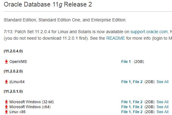
In my case, I will download "Microsoft Windows (X64)". There are two files. After extract both of files, I need to merge and make together in same directory. I copied and pasted whole directory from secondary to first.

After merge, I can see the directory inside. There is the "setup" icon. Click it.

Click Run and Start Installation for oracle database.

Depends on the system environments, Installer make warnning messages like this. However, I can ignore this, Click "yes"

Uncheck "I wish to receive security updates via My Oracle support", because I do not need this feature. It does not matter for next step. In email field, I can leave with empty. Just click "Next"

After Next, the warning message come. However it is also not matter for next step. Just click "yes".

Choose "Create and configure as a database". Because this is first installtion on this server. Click "Next".

In my case, my operating system is windows 2012 R2 server. Therefore, I will choose "Sever class".

I will install with standalone mode. Choose "single instance database installation" and click "Next".

Choose "Advanced Install" and Next.

This step is more important rather than before. In this insturction, there are some explain about the fields. I overview about below. 

Select "Langurage"

I will select "Standard Edition One" (Please note I can select what I want as the oracle database engine).

I select my custom home directory like below.

Select configuration type. In my case, I will choose genera purpose.

"Global database name" is not SID. However, I choosed single instance mode. Becuase of this, the SID can be same as Global database name. However, I can make different in Advanced mode.


I will adjust some paramters for memory, characters set, security and sample schema.

I will UTF-8 for character sets.

I will not make sample schema. Un-check "Create database with sample schema"

During this installation, Oracle Enterprise Manager will be installed, even if I do not want. Just click Next

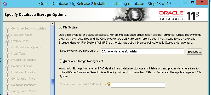
Select File system. Usually it is better to seperate from root disk.

This is the back up configuration. I don't want this at this time.

When I select "Typical Installation". There are Administrative password which is default password for schema (=users)

However, In Advanced mode, I can set password individually like below.


If you use simple password, the warnning message happen like below. In my case, this is test oracle database. I will ignore this. Click yes.

In advaced mode
In typical mode

This is summary, Click Finish to installation.

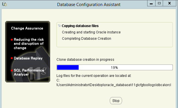
During installation, I can see the configuration assistant process like below.

During the installation, warnning message like below can be occure. In this case, I need to set variable in windows.

I will handle this later. At this time, just click next. I registered the "Administrative password" before. I have told it will be used as default password. However, I have another change to set the password for each schema (=user).

Click Password Management. I will set individual password for "SYS" and "SYSTEM". If you want more, you can set the password more. In oracle database, there are serveral sample test schema such as "HR" and "SCOTT".

Continue with Yes.


3. Access database


Now, I can access database. At this time, I can use sqlplus which is installed with.

I can access with SYSTEM schema account like below

4. Verify the oracle environment for enterprise manager.


During the installation, I see warning message below. Because of this, I need to check environment variables.

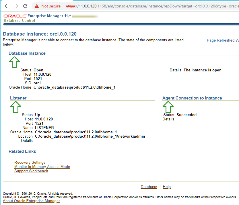
In this page, I need to check the status with "emctl status dbconsole"

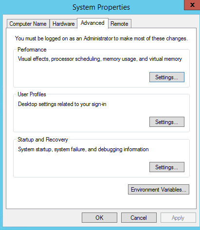
In this case, I need to set environment value. Properties > Advanced system settings.

In Advanced tap, there are environment value button.

I will add some values in User vriables for Administrator.

For the first issue, I will add "ORACLE_UNQNAME". 

I will reference the value from db_unique_name. In fact, there is value when environment is not set. run "select name,db_unique_name from v$database;".

I will try again "emctl status dbconsole". At this time, there is "Not found" error. 

Go into the directory. Thre is no localhost. Instead, 11.0.0.131 is existed.

To resolve this, I will add "ORACLE_HOSTNAME" like below.

After then, It will be like below. This is normal. However, It look like not perfect. "EM Daemon is not running" is happen.

I followed this video. To make success, I have to start service manually. At this time, I can not start after right button.

Find the file below. In emd properites file, "agentTZRegion=+06:00" should be adjusted with OS time.

I adjust the time 

Now, I can use this.


5. Oralce database stop, start and restart


In this instruction, there are several way to stop and start. In this part, I will overview sqlplus to stop and start.

6. Enable/Disable Archive log Mode


Sometime, it is necessary to enable this feature. It is utilized to synchronize databases with log-miner. For this, I will follow this instruction. run "archive log list". The result is displaied. It is not enabled default.

I need to shutdown with "shutdown immediate". My status is changed to "nolog".

I have to change the status to "mount", which I can change configuration on. Run "startup mount".

Run "alter database archivelog;" to enable

After then, I open the database "alter database open;"

If you want to disable, I use "alter database noarchivelog;"


7. Enable/Disable supplemental logging 


This action should be done in database. To check the status, run "select supplemental_log_data_min from v$database;"

To enable and disable, run query like below.

This is the basic configuration for the installation. 


Reference 


[ 1 ] https://www.youtube.com/watch?v=YgFfjLHY-wE

[ 2 ] https://medium.com/@Dracontis/how-to-install-oracle-11g-database-on-windows-server-2012-a4d30d4dc727

[ 3 ] https://www.oracle.com/technetwork/database/enterprise-edition/downloads/index.html

[ 4 ] https://docs.oracle.com/cd/E25178_01/server.1111/e10897/install.htm

[ 5 ] http://www.dba-oracle.com/t_oracle_unqname.htm

[ 6 ] http://blog.mclaughlinsoftware.com/2012/08/23/whats-oracle_unqname/

[ 7 ] https://www.youtube.com/watch?v=Y8i41J7aLwo

[ 8 ] https://docs.oracle.com/cd/B14117_01/win.101/b10113/admin.htm#CDCEJADC

[ 9 ] http://www.oracledistilled.com/oracle-database/backup-and-recovery/enabledisable-archive-log-mode-10g11g/


How to user the Oracle View and Joins (Inner and outer)


Recently, I have been studying about the Oracle Database. In this post, I wrote about the basic concept. In this post, I will handle about View and Joins.


1. Pre-requisite


I will create 2 tables like below.

create table MYADMIN.users ( name varchar2(15), id number(10) ) tablespace myspace;
create table MYADMIN.lessons ( id number(10), lessons varchar2(15), day varchar2(15) ) tablespace myspace;

insert into MYADMIN.users (name, id) values ( 'ant', 101 );
insert into MYADMIN.users (name, id) values ( 'bee', 102 );
insert into MYADMIN.users (name, id) values ( 'dog', 104 );


insert into MYADMIN.lessons (id, lessons, day) values ( 101, 'math', 'monday' );
insert into MYADMIN.lessons (id, lessons, day) values ( 102, 'art', 'tuseday' );
insert into MYADMIN.lessons (id, lessons, day) values ( 103, 'music', 'friday' );
insert into MYADMIN.lessons (id, lessons, day) values ( 105, 'exec', 'sunday' );

After run these command, I can get the tables with datas


Now, I am ready to start.


2. Inner and  Right, Left, Full Joins


I will follow this instructions. In this instructions, It has more detail. In this post, I will handle the way how to use this. Joins are one of filters with tables. Therefore, I can extract the matched data from tables.


2-1. Inner Join


As the figure, It shows the result after Inner Join. I can extract the matched data as intersection. This is the command. 

select name from MYADMIN.users inner join MYADMIN.lessons on MYADMIN.users.id = MYADMIN.lessons.id; 

This command means that I can extract intersection from both of "MYADMIN.users" table and "MYADMIN.lessons" table.


2-2. Left outer Join


With this option, Left side of tables are the source. This source start to compare data of the Right side of tables. When condition is matched. It extract matched data from both of table. However, the condition is not matched, the data from the source can be obtained but the data from right side of table inserted as the "<null>"

select MYADMIN.users.name, MYADMIN.lessons.day from MYADMIN.users left outer join MYADMIN.lessons on MYADMIN.users.id = MYADMIN.lessons.id; 


2-3. Right outer Join

This is reverse concept of the left outer join above. At this time, left side of tables is the source. Therefore, the value could be "<null>" from right side of tables, when condition does not match.

select MYADMIN.users.name, MYADMIN.lessons.day from MYADMIN.users right outer join MYADMIN.lessons on MYADMIN.users.id = MYADMIN.lessons.id; 

2-4. Full outer Join

With this option, left side and right side can be source. If the column from left side which does not exist in right side, this is the source. If the column from right side which does not exist in left side, this is also the source.  

select MYADMIN.users.name, MYADMIN.lessons.day from MYADMIN.users full outer join MYADMIN.lessons on MYADMIN.users.id = MYADMIN.lessons.id; 


3. Views


I will follow this instruction for this part. Views is the virtual table which is not existed in real. Sometime, I need to combine or make complex database query. In this case, this views is quite useful. For example, I will create view with the query of full outer join.

# create view

create view matched_info as select MYADMIN.users.name, MYADMIN.lessons.day from MYADMIN.users full outer join MYADMIN.lessons on MYADMIN.users.id = MYADMIN.lessons.id;


# select for query

select * from matched_info; 

I have already told that the view is not real table. Thus, I can not find out the information from "user_tables".

However, I can see the view information from "user_views". In the "TEXT", I can see the query which I used to create.

I think "the views is belonged to the schema (=user), even if it is virtual table". I can give some grant option like below.

grant select on MYADMIN.matched_info to MYUSER;


After login again with "MYUSER" account, I can show the data from this view also.

However, I can not show any detail information with "user_views" or "user_table".

Because, it only show the data whch is created by "schema". Therefore, if you want to see, you need to search through grant option like below.

If I want delete (drop) the view, Use this command below

drop view MYADMIN.matched_info;


Reference 


[ 1 ] https://www.techonthenet.com/oracle/joins.php

[ 2 ] https://createnetech.tistory.com/32

[ 3 ] https://www.techonthenet.com/oracle/views.php


How to use the Oracle database basically?


Recently, I need to study about the Oracle Database. In fact, I am not DBA. In this post, I will write the database queries to use later. I will use the Oracle SQL developer for this test.


1. Download and Connect database


I followed this instruction, which introduce how to connect to database. I need to download Oracle SQL developer from here. After download, I can connect database with connect button on the left of top.


2. Check the Database Properties.


select * from database_properties;


I can see configuration or properties from query like below. For example, I can see the "Default Temp Tablespace" which the user information is stored in.


3. Create (Drop) User


This is important part to understand about Oracle Database. In Oracle, there is "schema" term. I think this is also user. All of objects such as table are connected to this schema. For example, "schema.table_name" is used as the table name when I create table. This instruction show how to create user.


select * from dba_users;


I can get the all of users information in this database like below.


Now, I will create new user which is identified by the password.


create user virginiauser identified by password1;


I can see the new user created with "select * from dba_users;".


If you want to remove or revoke user, follows the command below.


drop user virginiauser;


4. Grant Privileges and role.


However, this user does not have any role and privileges. In this instruction, there are comments for roles.  


Role NameCreated By (Script)Description

CONNECT

SQL.BSQ

Includes the following system privileges: ALTER SESSION, CREATE CLUSTER, CREATE DATABASE LINK, CREATE SEQUENCE, CREATE SESSION, CREATE SYNONYM, CREATE TABLE, CREATE VIEW

RESOURCE

SQL.BSQ

Includes the following system privileges: CREATE CLUSTER, CREATE INDEXTYPE, CREATE OPERATOR, CREATE PROCEDURE, CREATE SEQUENCE, CREATE TABLE, CREATE TRIGGER, CREATE TYPE

DBA

SQL.BSQ

All system privileges WITH ADMIN OPTION

Note: The previous three roles are provided to maintain compatibility with previous versions of Oracle and may not be created automatically in future versions of Oracle. Oracle Corporation recommends that you design your own roles for database security, rather than relying on these roles.

EXP_FULL_DATABASE

CATEXP.SQL

Provides the privileges required to perform full and incremental database exports. Includes: SELECT ANY TABLE, BACKUP ANY TABLE, EXECUTE ANY PROCEDURE, EXECUTE ANY TYPE, ADMINISTER RESOURCE MANAGER, and INSERT, DELETE, and UPDATE on the tables SYS.INCVID, SYS.INCFIL, and SYS.INCEXP. Also the following roles: EXECUTE_CATALOG_ROLE and SELECT_CATALOG_ROLE.

IMP_FULL_DATABASE

CATEXP.SQL

Provides the privileges required to perform full database imports. Includes an extensive list of system privileges (use view DBA_SYS_PRIVS to view privileges) and the following roles: EXECUTE_CATALOG_ROLE and SELECT_CATALOG_ROLE.

DELETE_CATALOG_ROLE

SQL.BSQ

Provides DELETE privilege on the system audit table (AUD$)

EXECUTE_CATALOG_ROLE

SQL.BSQ

Provides EXECUTE privilege on objects in the data dictionary. Also, HS_ADMIN_ROLE.

SELECT_CATALOG_ROLE

SQL.BSQ

Provides SELECT privilege on objects in the data dictionary. Also, HS_ADMIN_ROLE.

RECOVERY_CATALOG_OWNER

CATALOG.SQL

Provides privileges for owner of the recovery catalog. Includes: CREATE SESSION, ALTER SESSION, CREATE SYNONYM, CREATE VIEW, CREATE DATABASE LINK, CREATE TABLE, CREATE CLUSTER, CREATE SEQUENCE, CREATE TRIGGER, and CREATE PROCEDURE

HS_ADMIN_ROLE

CATHS.SQL

Used to protect access to the HS (Heterogeneous Services) data dictionary tables (grants SELECT) and packages (grants EXECUTE). It is granted to SELECT_CATALOG_ROLE and EXECUTE_CATALOG_ROLE such that users with generic data dictionary access also can access the HS data dictionary.

AQ_USER_ROLE

CATQUEUE.SQL

Obsoleted, but kept mainly for release 8.0 compatibility. Provides execute privilege on DBMS_AQ and DBMS_AQIN.

AQ_ADMINISTRATOR_ROLE

CATQUEUE.SQL

Provides privileges to administer Advance Queuing. Includes ENQUEUE ANY QUEUE, DEQUEUE ANY QUEUE, and MANAGE ANY QUEUE, SELECT privileges on AQ tables and EXECUTE privileges on AQ packages.

SNMPAGENT

CATSNMP.SQL

This role is used by Enterprise Manager/Intelligent Agent. Includes ANALYZE ANY and grants SELECT on various views.


In my case, I am AWS Oracle RDS database. Look at the role assigned.


select * from dba_role_privs;


There are so many roles assigned.  There is no any role in user created before. However, there are so many role assigned for 'RDSADMIN' and master account.


RDSADMIN CRENETADMIN
XDBADMIN XDBADMIN
EXECUTE_CATALOG_ROLE EXECUTE_CATALOG_ROLE
CTXAPP CTXAPP
DATAPUMP_IMP_FULL_DATABASE DATAPUMP_EXP_FULL_DATABASE
OPTIMIZER_PROCESSING_RATE OPTIMIZER_PROCESSING_RATE
CAPTURE_ADMIN CAPTURE_ADMIN
IMP_FULL_DATABASE IMP_FULL_DATABASE
AQ_ADMINISTRATOR_ROLE AQ_ADMINISTRATOR_ROLE
EM_EXPRESS_BASIC EM_EXPRESS_BASIC
EM_EXPRESS_ALL EM_EXPRESS_ALL
DELETE_CATALOG_ROLE DELETE_CATALOG_ROLE
SODA_APP SODA_APP
RECOVERY_CATALOG_USER RECOVERY_CATALOG_USER
CONNECT CONNECT
OEM_ADVISOR OEM_ADVISOR
OEM_MONITOR OEM_MONITOR
SELECT_CATALOG_ROLE SELECT_CATALOG_ROLE
HS_ADMIN_SELECT_ROLE HS_ADMIN_SELECT_ROLE
DBA DBA
RESOURCE RESOURCE
  RDS_MASTER_ROLE
DATAPUMP_EXP_FULL_DATABASE DATAPUMP_IMP_FULL_DATABASE
XDB_SET_INVOKER XDB_SET_INVOKER
GATHER_SYSTEM_STATISTICS GATHER_SYSTEM_STATISTICS
SCHEDULER_ADMIN SCHEDULER_ADMIN
RECOVERY_CATALOG_OWNER RECOVERY_CATALOG_OWNER
HS_ADMIN_EXECUTE_ROLE HS_ADMIN_EXECUTE_ROLE
AQ_USER_ROLE AQ_USER_ROLE
EXP_FULL_DATABASE EXP_FULL_DATABASE


Now I will give 3 role for user which I created like below.


grant connect, resource, dba to virginiauser;


After this I can check the role status.


So far, I studied how to grant the privileges. However, I need to revoke these sometimes. 


revoke connect, resource, dba from virginiauser;


After granting roles to user, I need to give some privileges to this user. In oracle, there are two types of privileges, system and table.  At first, I will grant some privileges for the system.


RDSADMIN CRENETADMIN
INHERIT ANY PRIVILEGES  
GRANT ANY OBJECT PRIVILEGE GRANT ANY OBJECT PRIVILEGE
DROP ANY DIRECTORY DROP ANY DIRECTORY
UNLIMITED TABLESPACE UNLIMITED TABLESPACE
EXEMPT REDACTION POLICY EXEMPT REDACTION POLICY
CHANGE NOTIFICATION CHANGE NOTIFICATION
FLASHBACK ANY TABLE FLASHBACK ANY TABLE
ALTER SYSTEM  
ALTER PUBLIC DATABASE LINK ALTER PUBLIC DATABASE LINK
EXEMPT ACCESS POLICY EXEMPT ACCESS POLICY
ALTER DATABASE  
SELECT ANY TABLE SELECT ANY TABLE
RESTRICTED SESSION RESTRICTED SESSION
ALTER DATABASE LINK ALTER DATABASE LINK
CREATE EXTERNAL JOB  
EXEMPT IDENTITY POLICY EXEMPT IDENTITY POLICY
ADMINISTER DATABASE TRIGGER  
GRANT ANY ROLE  


I can give(remove) some system privileges like below.


grant UNLIMITED TABLESPACE TO myadmin;

revoke UNLIMITED TABLESPACE from myadmin;


After this, I can verify the status with "select * from dba_sys_privs" query.


Now, the table privileges left. In fact, I can not explain about this without the table. I will add more detail later in this post. Just look at the command how to see.


select * from dba_tab_privs where grantee='CRENETADMIN';


5. Create(Drop) Table


Before I create the Data table, I need to create table space. In this instruction, what kinds of parameters are required is explained. This command show the table spaces list. 


select * from dba_tablespaces;


There are some necessary factor for this table space. Fist is "Contents". There are three values to category. In the instruction, there are comments like below.


A permanent tablespace contains persistent schema objects. Objects in permanent tablespaces are stored in datafiles.


An undo tablespace is a type of permanent tablespace used by Oracle Database to manage undo data if you are running your database in automatic undo management mode. Oracle strongly recommends that you use automatic undo management mode rather than using rollback segments for undo.


A temporary tablespace contains schema objects only for the duration of a session. Objects in temporary tablespaces are stored in tempfiles. 


From this statements above, "Undo tablespace" is not friendly rather than others. Please, read these instructions, https://oracle-base.com/articles/9i/automatic-undo-management and https://docs.oracle.com/cd/B28359_01/server.111/b28310/undo002.htm#ADMIN11462. For this "Undo tablespace",  "automatic undo management" is required. The recently version is set as defaults. Also, I tried to change this configuration in AWS RDS. Howerer, I can not alter this.


Second is the datafile conecpt such as "bigfile" or "smallfile". In this instruction


A bigfile tablespace contains only one datafile or tempfile, which can contain up to approximately 4 billion (232) blocks. The maximum size of the single datafile or tempfile is 128 terabytes (TB) for a tablespace with 32K blocks and 32TB for a tablespace with 8K blocks.


A smallfile tablespace is a traditional Oracle tablespace, which can contain 1022 datafiles or tempfiles, each of which can contain up to approximately 4 million (222) blocks. 


From this statements, I can not understand "smallfile tablespace can contain multiple datafiles". Please look at this link


create tablespace homeworkts 

datafile 'D:\oradata\orcl\df1.dbf' size 4m, 

         'D:\oradata\orcl\df2.dbf' size 4m, 

         'D:\oradata\orcl\df3.dbf' size 4m; 


However, this command does not work in AWS RDS. Because RDS does not give any permission for this like below. I can not create the datafile.


There are so many options, however I can not handle all of things. I think I can create tablespace with these information. I hope this instruction will be helpful.


# Permament-Bigfile tablespace

create bigfile tablespace myspace;


# Permament-Bigfile tablespace

create bigfile temporary tablespace mytemp;


After this command, I can see the "select * from dba_tablespaces;" and "select * from dba_data_files;"


select tablespace_name,contents,bigfile from dba_tablespaces;


select file_name,tablespace_name,autoextensible from dba_data_files;


Now, I created table spaces. I can start to create table. Please look at this, there are sample example to create table. 


create table user.info ( name varchar2(15), id number(10) ) tablespace myspace;


This command create "error" like below. This error is occurred by table name.


In oracle, table name must be "schema (=user)"+"table name". This is the reason why the schema (=user) is import. Because of this, I have to revise the command below. "MYADMIN" is created user before.


create table MYADMIN.user_info ( name varchar2(15), id number(10) );


After this command I can see the table information with "select * from dba_tables;"


select * from dba_tables;

select * from dba_tables where owner='MYADMIN';


There are 2 things special. I insert "MYADMIN.user_info" as the table name. Howerver, oracle re-arrange this table name with "owner" and "table_name". Also, "USERS" tablespace is allocated for this table, which is default permanent tablespace. However I want that this table is located in "MYSAPCE" table space. Thus, it should be revised like below.


create table MYADMIN.user_info ( name varchar2(15), id number(10) ) tablespace myspace;


However, I can create this. Because this table name has already existed. Thus I need to drop this table with this command.


drop table MYADMIN.user_info;


Now, this is what I want.


6. Insert, Update, Delete Data


Before start this part, I need to covert account with "MYADMIN", which is used as the "schema name".


select * from user_tables;


"user_tables" show the information which belonged to logon account. If I can see table only I create, it is OK.


However, there is other way to find out logon current user. In this instruction, "select user from dual;" is command.


select user from dual;


I will follow this instruction. At first, I will try to insert some data into "user_info" table;


insert into user_info (id, name) values (101,'fox');

insert into MYADMIN.user_info (id, name) values (102,'wolf');


Please note that I can use both of "schema+table name" and "table name", because the current user is same as the schema name. After this command, look at the table information like below.


select * from MYADMIN.user_info;


Now, I will update the data. Please note I use "schema+table name" as the table name. It does not affect the result.


update MYADMIN.user_info set ID=103 where name='wolf';


Finally, Delete is left. This is not difficult to run.


delete from user_info where id=103;


7. Troubleshooting. (table privileges with other schema)


I am happy to learn how to insert, update and delete data. However, I need to think about my privileges. So far, I did not give any permission about table. The reason why this can be done is that this user is the "schema user". It look like admin user for this table. If I create another user (=schema), I wonder if this user can insert, update and delete with this table.


# create new (another) user

create user myuser indentified by myuser;


This user does not any role and privileges at the beginning. 


I can not logon into the Database. I add the role with "connect"


grant connect to myuser;


Now, I can login. However, I can not select, insert, update and delete over table. I need to give some privileges.


With administrator account, I will give this user some permissions. Please, look at the this instruction.


grant select, insert, update, delete on MYADMIN.user_info to MYUSER;

Now, I can select, insert, update and delete.


If I want to know what kinds of table privileges does this user has, use this command


select * from dba_tab_privs where grantee='MYUSER';


This is basic oracle database concept. I hope it will be helpful. If I have enough time to learn, I will handle more. However, I am not DBA engineer. I hope I can keep touch about this part again.


Reference


[ 1 ] https://docs.aws.amazon.com/ko_kr/AmazonRDS/latest/UserGuide/USER_ConnectToOracleInstance.html

[ 2 ] https://www.oracle.com/technetwork/developer-tools/sql-developer/downloads/index.html

[ 3 ] https://docs.oracle.com/cd/B28359_01/server.111/b28286/statements_8003.htm#SQLRF01503

[ 4 ] https://chartio.com/resources/tutorials/how-to-create-a-user-and-grant-permissions-in-oracle/

[ 5 ] https://docs.oracle.com/cd/B19306_01/server.102/b14200/statements_7003.htm

[ 6 ] https://stackoverflow.com/questions/8496152/how-to-create-a-tablespace-with-multiple-datafiles

[ 7 ] https://docs.oracle.com/en/database/oracle/oracle-database/12.2/sqlrf/CREATE-TABLESPACE.html#GUID-51F07BF5-EFAF-4910-9040-C473B86A8BF9

[ 8 ] https://www.java2s.com/Code/Oracle/User-Previliege/Getcurrentusername.htm

[ 9 ] https://www.oracle-dba-online.com/sql/insert_update_delete_merge.htm

How does the flannel work?


Recently, I am studying kubernetis. During studying, I have known about the flannel. There is some instruction to reproduct simply. I will follow this instruction.


1. Pre-requisite


There are some preparation. Docker and Etcd should be installed before. Here is instruction for installation of Docker. I will install community engine on 2 nodes running "ubuntu 16.04".


sudo apt-get remove docker docker-engine docker.io

sudo apt-get update

sudo apt-get install \

    apt-transport-https \

    ca-certificates \

    curl \

    software-properties-common

curl -fsSL https://download.docker.com/linux/ubuntu/gpg | sudo apt-key add -

sudo apt-key fingerprint 0EBFCD88

sudo add-apt-repository \

   "deb [arch=amd64] https://download.docker.com/linux/ubuntu \

   $(lsb_release -cs) \

   stable"

sudo apt-get update

sudo apt-get install docker-ce  


And then, I will install Etcd. I have already written how to install and use Etcd in this post. However, it is more simple in this instruction. In my case, I will run the command in "root directory"


wget https://github.com/coreos/etcd/releases/download/v3.0.12/etcd-v3.0.12-linux-amd64.tar.gz

tar zxvf etcd-v3.0.12-linux-amd64.tar.gz

cd etcd-v3.0.12-linux-amd64


After installation, I will edit the "/etc/hosts" file before running this Etcd. Please note that host name has only single IP address on this file.


vi /etc/hosts

147.75.65.69    node1

147.75.65.63    node2


Each nodes can communicate with each other with these IP addresses.


# At node 1

nohup ./etcd --name docker-node1 --initial-advertise-peer-urls http://node1:2380 \

--listen-peer-urls http://node1:2380 \

--listen-client-urls http://node1:2379,http://localhost:2379 \

--advertise-client-urls http://node1:2379 \

--initial-cluster-token etcd-cluster \

--initial-cluster docker-node1=http://node1:2380,docker-node2=http://node2:2380 \

--initial-cluster-state new&


# At node 2

nohup ./etcd --name docker-node2 --initial-advertise-peer-urls http://node2:2380 \

--listen-peer-urls http://node2:2380 \

--listen-client-urls http://node2:2379,http://localhost:2379 \

--advertise-client-urls http://node2:2379 \

--initial-cluster-token etcd-cluster \

--initial-cluster docker-node1=http://node1:2380,docker-node2=http://node2:2380 \

--initial-cluster-state new&


Now, I am ready to start the flannel configuration.


cd etcd-v3.0.12-linux-amd64

./etcdctl cluster-health

member 43bb846a7344a01f is healthy: got healthy result from http://node2:2379

member a9aee06e6a14d468 is healthy: got healthy result from http://node1:2379

cluster is healthy


2. Flannel installation.


Download and install the flannel command on each nodes. In my case, I will run the command in "root directory"


wget https://github.com/coreos/flannel/releases/download/v0.6.2/flanneld-amd64 -O flanneld && chmod 755 flanneld


I will make configuration file to create the network topology.


vi flannel-network-config.json

{

    "Network": "172.16.0.0/12",

    "SubnetLen": 24,

    "SubnetMin": "172.16.16.0",

    "SubnetMax": "172.31.247.0",

    "Backend": {

        "Type": "vxlan",

        "VNI": 172,

        "Port": 8889

    }

}


In this documentation, there are the meaning of the above parameters. Especially, "SubnetLen" is IP address range allocated in each host. Flannel use the configuration from Etcd, /coreos.com/network/config. I will set the configuration on Node 1


# At node 1

cd etcd-v3.0.12-linux-amd64/

~/etcd-v3.0.12-linux-amd64$ ./etcdctl set /coreos.com/network/config < ../flannel-network-config.json


I can check if the configuration is set or not on Node 2.


# At node 2

cd etcd-v3.0.12-linux-amd64/

~/etcd-v3.0.12-linux-amd64$ ./etcdctl get /coreos.com/network/config | jq .

{

  "Network": "172.16.0.0/12",

  "SubnetLen": 24,

  "SubnetMin": "172.16.16.0",

  "SubnetMax": "172.31.247.0",

  "Backend": {

    "Type": "vxlan",

    "VNI": 172,

    "Port": 8889

  }

}


Now, I am ready to start the flannel. Before start flannel, I have to look at my network interface status.


# At node 1

nohup sudo ./flanneld -iface=bond0 &


# At node 2

nohup sudo ./flanneld -iface=bond0 &


After start flannel, I can see new interface which is named with "flannel.VNI". In this case, It should be flannel.172.


flannel.172 Link encap:Ethernet  HWaddr 82:41:de:d4:77:d3

          inet addr:172.16.75.0  Bcast:0.0.0.0  Mask:255.240.0.0

          inet6 addr: fe80::8041:deff:fed4:77d3/64 Scope:Link

          UP BROADCAST RUNNING MULTICAST  MTU:1450  Metric:1

          RX packets:0 errors:0 dropped:0 overruns:0 frame:0

          TX packets:0 errors:0 dropped:8 overruns:0 carrier:0

          collisions:0 txqueuelen:0

          RX bytes:0 (0.0 B)  TX bytes:0 (0.0 B)


Also, I can get some information from Etcd.


cd etcd-v3.0.12-linux-amd64/

~/etcd-v3.0.12-linux-amd64# ./etcdctl ls /coreos.com/network/subnets

/coreos.com/network/subnets/172.16.68.0-24

/coreos.com/network/subnets/172.16.75.0-24


This mean that each host has these subnets each. I can see more detail. 


cd etcd-v3.0.12-linux-amd64/

~/etcd-v3.0.12-linux-amd64# ./etcdctl get /coreos.com/network/subnets/172.16.68.0-24 | jq .

{

  "PublicIP": "147.75.65.63",

  "BackendType": "vxlan",

  "BackendData": {

    "VtepMAC": "7a:ac:15:15:2b:61"

  }

}


This is configuration for the flannel. I can also see the what flannel network is assigned with "/var/run/flannel/subnet.env". Please note that this file will be used for next step, docker daemon configuration.


cat /var/run/flannel/subnet.env

FLANNEL_NETWORK=172.16.0.0/12

FLANNEL_SUBNET=172.16.68.1/24

FLANNEL_MTU=1450

FLANNEL_IPMASQ=false


3. Docker daemon configuration.


Docker does not use flannel default. It has swarm mode to make overlay network. Therefore, it is necessary to change to use this flannel as default network module. At first, I have to stop the Docker daemon on each hosts, node1 and node2.


# Node 1 and Node 2

sudo service docker stop


I will restart Docker daemon with this flannel configuration.


# Node 1 and Node 2

source /run/flannel/subnet.env
sudo ifconfig docker0 ${FLANNEL_SUBNET}
sudo dockerd --bip=${FLANNEL_SUBNET} --mtu=${FLANNEL_MTU} &


Before restart Docker daemon, there is "docker0" interface default which has "172.17.0.1" IP address. It will be changed with the network what I defined.


# Before restart with flannel configuration

ifconfig docker0

docker0   Link encap:Ethernet  HWaddr 02:42:f6:10:ac:49

          inet addr:172.17.0.1  Bcast:172.17.255.255  Mask:255.255.0.0

          UP BROADCAST MULTICAST  MTU:1500  Metric:1

          RX packets:0 errors:0 dropped:0 overruns:0 frame:0

          TX packets:0 errors:0 dropped:0 overruns:0 carrier:0

          collisions:0 txqueuelen:0

          RX bytes:0 (0.0 B)  TX bytes:0 (0.0 B)


# After restart with flannel configuration

ifconfig docker0
docker0   Link encap:Ethernet  HWaddr 02:42:f6:10:ac:49
          inet addr:172.16.75.1  Bcast:172.16.75.255  Mask:255.255.255.0
          UP BROADCAST MULTICAST  MTU:1500  Metric:1
          RX packets:0 errors:0 dropped:0 overruns:0 frame:0
          TX packets:0 errors:0 dropped:0 overruns:0 carrier:0
          collisions:0 txqueuelen:0
          RX bytes:0 (0.0 B)  TX bytes:0 (0.0 B)


4. Create the Test container and Start it.


Now, I will create 2 container for the test. 


# At the node 1

sudo docker run -d --name test1  busybox sh -c "while true; do sleep 3600; done"


# At the node 2

ssudo docker run -d --name test2  busybox sh -c "while true; do sleep 3600; done"


Depends on the container properties, the container can be stopped after exit. "sh -c "while true; do sleep 3600; done" make this container keep alive for 1 hour. It is enough for the test.


5. Analysis container networks.


In this post, I will explain how to work in docker swarm mode. It is good to analysis the network topology of docker. At first, go to "/var/run/docker", there is the "netns" directory. There is the network configuration of the container.


# At node 1 and node 2 

cd /var/run/

ln -s docker/netns/ netns


After this symbolic link, I can see the network namespace list like below. "ip netns list" show the namespace ID.


ip netns list

faf9928b897f (id: 0)


I can see more detail information with this ID. "ip netns exec" show the same result with "docker exec". Thus I can see the same result with "docker exec test1 ip -d addr show"


# At the Node 1

ip netns exec b5380e6b336a ip -d addr show

1: lo: <LOOPBACK,UP,LOWER_UP> mtu 65536 qdisc noqueue state UNKNOWN group default qlen 1

    link/loopback 00:00:00:00:00:00 brd 00:00:00:00:00:00 promiscuity 0

    inet 127.0.0.1/8 scope host lo

       valid_lft forever preferred_lft forever

11: eth0@if12: <BROADCAST,MULTICAST,UP,LOWER_UP> mtu 1450 qdisc noqueue state UP group default

    link/ether 02:42:ac:10:4b:02 brd ff:ff:ff:ff:ff:ff link-netnsid 0 promiscuity 0

    veth

    inet 172.16.75.2/24 brd 172.16.75.255 scope global eth0

       valid_lft forever preferred_lft forever


# At the Node 2

ip netns exec faf9928b897f ip -d addr show

1: lo: <LOOPBACK,UP,LOWER_UP> mtu 65536 qdisc noqueue state UNKNOWN group default qlen 1

    link/loopback 00:00:00:00:00:00 brd 00:00:00:00:00:00 promiscuity 0

    inet 127.0.0.1/8 scope host lo

       valid_lft forever preferred_lft forever

15: eth0@if16: <BROADCAST,MULTICAST,UP,LOWER_UP> mtu 1450 qdisc noqueue state UP group default

    link/ether 02:42:ac:10:44:02 brd ff:ff:ff:ff:ff:ff link-netnsid 0 promiscuity 0

    veth

    inet 172.16.68.2/24 brd 172.16.68.255 scope global eth0

       valid_lft forever preferred_lft forever


6. Test and Troubleshooting


Now, I have know that "172.16.75.2" is container IP address on Node 1 and "172.16.68.2" is container IP address on Node 2. Flannel offers the overlay network between hosts. So, I will send ICMP (ping) from node1 to node2


ip netns exec b5380e6b336a ping 172.16.68.2

PING 172.16.68.2 (172.16.68.2) 56(84) bytes of data.

^C

--- 172.16.68.2 ping statistics ---

6 packets transmitted, 0 received, 100% packet loss, time 5040ms


Hmm. It does not work. From Docker 1.13 default iptables policy for FORWARDING is DROP,


# At Node 1 and Node 2

sudo iptables -P FORWARD ACCEPT


Wow, I can send ICMP each other.


ip netns exec b5380e6b336a ping 172.16.68.2

ip netns exec b5380e6b336a ping 172.16.68.2 -c 4

PING 172.16.68.2 (172.16.68.2) 56(84) bytes of data.

64 bytes from 172.16.68.2: icmp_seq=1 ttl=62 time=0.364 ms

64 bytes from 172.16.68.2: icmp_seq=2 ttl=62 time=0.310 ms

64 bytes from 172.16.68.2: icmp_seq=3 ttl=62 time=0.319 ms

64 bytes from 172.16.68.2: icmp_seq=4 ttl=62 time=0.308 ms


--- 172.16.68.2 ping statistics ---

4 packets transmitted, 4 received, 0% packet loss, time 2998ms

rtt min/avg/max/mdev = 0.308/0.325/0.364/0.026 ms


This is the flannel.


Reference


[ 1 ] https://docs.docker.com/install/linux/docker-ce/ubuntu/

[ 2 ] https://docker-k8s-lab.readthedocs.io/en/latest/docker/docker-etcd.html

[ 3 ] https://docker-k8s-lab.readthedocs.io/en/latest/docker/docker-flannel.html

[ 4 ] https://github.com/coreos/flannel/blob/master/Documentation/configuration.md

How to use AWS AppStream 2.0?


Have you ever used "Google Docs"? In this case, there is no host like PC. AppStream make like this. I can access my application from outside, such as Internet. AppStream has some advantage and disadvantage. It is simple to access and manage. Also it is more secure. Because the user can not do other things on this host. However, It is not easy to deploy with right size, even if AWS offer auto-scaling. I need to how much use can be used at the same time. Most of this post are referenced by this.


1. Create Image


AppStream is auto-scaling system. Thus, I need customized standard image to deploy.  In this image, I can install my application. It will be deployed. Please note that I will set this instance to create image over the subnet which can communicate with Internet, however the real-instance can be located over the private subnet which can not communicate with Internet. In Images, there are 2 category, Image Registry and Image Builder. At the first, I will select Image Builder to create my image which is installed for terminal. Launch Image Builder. 


Now, I need to select basic OS to create my image. In my case, I will choose Windows 2012 R2, which is named wit "Base-Image-Builder-06-12-2018". Please note this image can be different by the AWS Region.


Insert the image name and select the type for CPU and Memory. These parameters can not changed after first creation. Thus, I need another images when I need other size of instance.


Select the network which the instance attach to. Please note that this is the network only for image creation. When the real-system is deployed, I can define the network. I will touch at the next time. In this case, I need to download terminal tools from Internet. Thus, this instance will be located over the subnet which can communicate with Internet.


The subnet should be routed with NAT gateway. AppStream does not assign EIP. Thus, It is not possible to download from Internet, if the instance is located over the sunbet with Internet gatway.


Review and Launch.


2. Connect Image


Now, I need to install my application on the launched image. After status change from Pending to Running, I can connect this image.


After connect, I can see the screen like below. I need to select user to login. At this time, I will select "Administrator" at the first.


Now, I can see the windows which is login with "Administrator" account. Open the CMD and Run "ipconfig" to see the network interface information. There are 2 interface. "11.8.48.79" is interface which is one of VPC subnet network. "198.19.168.187" is the interface which offer the display for users. "198.19.168.187" interface is controlled by AWS managed. Most of traffic is pass through the "11.8.48.79" interface. I can download some files from this interface.


On the desktop, there is firefox. Open this and write "https://www.putty.org/". In my case, I will download "Putty" for the sample application.


After download the file, (Default, the downloaded file will be located in documents directory), Install this application.


Please remember the installation path for the next step. In this case, the putty is installed under "C:\Programs". After installation, close all of windows. In the desktop, I can see the "Image Assistant". This application help me to register my application for the AWS AppStream.


AppStream 2.0 Image Assistant application should be run. Follow the step by this application.


3. AppStream 2.0 Image Assistant.


I need to register my application for AppStream 2.0. Click "Add App", Find out the running file. 


"App Launch Setting" menu is opened. In this instruction, there are more information about this. "Launch Parameters" and "Working Directory" are depend on my application. In this case, I will leave blank.. Just click "Save"


Click "Next"


This is important step. In this part, I can customize my application. I need to re-login with Template User. In this mode, I can define my application how to work. Click "Switch User"


Select "Template User"


After login, I can change OS configuration and Application settings. In my case, I will register sample session information. "my-sample" session information is updated over my application.


Also, I can run this application with what I want to do. I open SSH to my sample host.


I have done all of things. In the desktop, there is Images Assistant is located. Run it. And back to main with Administrator account.


Select "Administrator" and login again.


After login, I can see "Save settings" button activated. Click this button and click "Next"


Now, I have to verify if this application work correctly. I will switch user with "user" account.


Select "Test User"


After login, I can run "Putty" again. And I can confirm that "my-sample" session in configuration is remained.


Run "Images Assistant" in the desktop, and go back to main with "Administrator" account.


Select "Administrator" again.


Now, I am ready to finish. Launch.


After complete to launch, click continue.


Fill with image name.


Review and Create Image.


The viewer will be disconnected. And the building image will be started.


It will take about 10~20 minutes. And then, I can see the my image on AWS console.


4. Snapshotting Image. 


During the time, I can see the AWS console to check the status. In the "Image Registry", there is "image" which is creating. 


In "Image Builder", my based image has the status "Snapshotting". Please note that I can not do any action in this "Snapshotting" status.


I can expect that "Snapshotted image" is registered in Image Registry.


5. Delete Image in "Image Builder" (Optional)


There is no relationship between image in registry and image in builder. So, I can delete and remove this image in the builder. If you have change to make another type of image include configuration, I will remain this image. However, this is not necessary in this post. I also show the relationship between them.


After the status is "Stopped", I can delete this image.


6. Create fleet.


I have a image which I want to deploy. I need to define the network to deploy. The fleet has this kinds of role. Create Fleet.


Insert Name for this fleet.


I can see my image which has been created. Select the image and Next.


From here, network and security, capacity for scaling are defined. Select type of CPU and RAM for this instance. This is not changeable. If I want to change, I need to create another fleet. In fleet type, there are 2 modes, "On-Demand" and "Always-on". I want to save my money, so I will select "On-Demand"


Maximum session duration means "User can stay during this time once". Disconnect timeout means "After session finish, this instance can not re-assign to other user until this time spent". Minimum and Maximum capacity define the number of con-current session. AppStream offer auto-scaling, however, it take 10~20 minutes. It is too long, therefore, I need to define with proper number. In Scaling detail, this is the parameters to scale-out.


In here, the nework and security group is defined. I can locate AppStream instance into the subnet which does not communicate with Internet. In image builder step, I located at the subnet which communicate with Internet.


Review and Create.


Now I have a fleet.


7. Create Stack and Connect with Fleet


Stack has the role to define "User Pattern". Create Stack


Insert Name


I can define if I use Home Folders for each sessions. In my case, I do not want that the user remain their files on the instance. Because this instance will be shared with others. Default, it is enabled. However, I disable the option.


I can also user behavior such as "Copy and Pasts" usages. Just define what you want.


Review and Create.


After creation of stack, I need to associate fleet. In Actions, there is "Associate Fleet".


Select the fleet which is created before,


And confirm the stack details. If you want to remove fleet, you have to dis-associate this relationship at first.


8. Create User Pool.


In workspace, I need AD system. Fortunately AppStream offer this feature through AWS console. Create User.


Insert information for user. The Email address should be correct. The access link, account and temporary password are sent to this email address.


After creation of user, I need to associate with stack. I associate with the stack already created. 


Select the stack.


Look at the details, I will resend welcom email which is include access link.


I will received this email.


9. Accessing and Login the AppStream.


Click the Link which is include in email. New windows is opened like below.


After first login, I need to change my password.


Re-login and I can see like below. I registered the putty application only. Therefore, Putty Icon is appeared.


I can see the my application opened.


This is the AWS AppStream, I hope this post help you!


10. Troubleshooting


10-1. Remote User.


In the AWS console, I can not delete the user. It is only possible with API. I will use awscli command.


aws appstream delete-user --user-name xxxxxxx@xxxxxxx --authentication-type USERPOOL


10-2. Delete S3 bucket


AppStream can save Home folders and Application configuration in S3 bucket. This bucket will be created automatically. When I delete this S3 bucket, I can not make success. Because there are some limitation to protect S3 bucket. So I have to change this part at the first to remove.


After clear in Bucket Policy, I can remote this bucket.


Reference


[ 1 ] https://docs.aws.amazon.com/appstream2/latest/developerguide/tutorial-image-builder.html

[ 2 ] https://d1.awsstatic.com/product-marketing/AppStream2.0/Amazon%20AppStream%202.0%20Getting%20Started%20Guide%20April%202018.pdf

[ 3 ] https://docs.aws.amazon.com/appstream2/latest/developerguide/managing-network.html

[ 4 ] https://docs.aws.amazon.com/cli/latest/reference/appstream/delete-user.html

How to use AWS workspace?


Recently, I have some chance to do simple test for AWS workspace. Deploy is not difficult. However, there are some necessary factor to do best architecture.


1. Pre-requsite.


The AD system should be necessary, For this post, I will use AWS managed Microsoft AD service. I write a post which explain how to configure it. In directories, I can see the "Registered" directory.


2. Install and Configure for AWS workspace.


Launch Workspace at first.


Select the directory which I have create already. This directory offer user management service.


Select the user which I want to use. In my case, I will use AWS managed AD service. I have already created "crenetadmin" user in AD. Please note that, User information required First, Last name and E-mail address. (Please note a user can be assigned for single workspace only. I need other user for secondary worksapce.)


Select the OS type. In my case, I will select "Standard with WIndows 10".


Select "Running Mode", I will select "AutoStop" mode., which make the instance stopped when no usage is happend.


Review and Launch it.


3. Login and Run the AWS workspace.


In the detail after launching, I can see the client link "https://clients.amazonworkspaces.com/". From this, I can download client program. Also, weblogin is possible.


I have to remember the "Registration Code". Click "Web Access Login", and then I can see the Registration page.


On this page, I will insert Registration code.


If I meet this error message, I need client downloaded.


After download and Installation of AWS workspace client, I can see the I-con over desktop and I run it.


At the beginning, I can see the field to insert "Registration code". However, aT the left corner of the top, there are configuration button. Under this button, I can see "Manage Registrations". After Registration, I can see the login step.


With the username and password which are registered on AWS managed AD service. I can pass the next step. Select what I want.


Now, I can use workspace.


4. Troubleshooting and Deep-dive for AWS workspace.


However, this is so strange. I have not defined any network and security information. Look at the network interface information. 


This is other case. In this case, 11.5.80.110 is assigned.


There are 2 interface. "11.5.64.253" is the one of VPC network and "198.19.113.72" is new network which I have not known


And I try to send ICMP packets, one is for internet connection and the other is for internal connection. I will explain why this kinds of situation is happened. During the creation of the AWS managed Microsoft AD from this post, I selected 2 subnets. At this time, I selected subnets which is not possible for outbund traffic. Thus IP address for this workspace is assigned by this subnets. "11.5.64.253" is the one of IP address which the directory service have"198.19.113.72" is the secondary IP address, which make connection from the user with client and weblogin. Therefore, I need to consider this properties to architecture for this service.


5. Security and Service Port


If you are use the internet network to access this workspace, it does not matter. However, if you are inside of the company, sometimes you need to open the firewall security policy for this service. you make huge trouble. It is not easy. Please refer this link https://docs.aws.amazon.com/ko_kr/workspaces/latest/adminguide/workspaces-port-requirements.html


Reference 


[ 1 ] http://createnetech.tistory.com/27

[ 2 ] https://docs.aws.amazon.com/ko_kr/workspaces/latest/adminguide/workspaces-port-requirements.html

How SSL/TLS handshake can be done?


In this post, I will analysis the SSL/TLS packet. In fact, I have some chance to see RDP packets. Look at the below. This is RDP packet captures. 


I wrote "How to calculate the sequence number" in this post. In this post, I will only handle how SSL/TLS handshake can be done. Before SSL/TLS handshake, TCP handshake should be established.


1. Client Hello


At first, Client send the "Client Hello" packet. In this packet, there are three important information. Random number, Session ID and Cipher suites


Random number is used to generate "pre-master key" with another random number from server. This "pre-master key" will be used to generate "master key" which encrypt and decrypt the packets.

Cipher suites is the list which the client can support. Thus, the server will select one of this lists.


2. Server Hello.


After receive the client hello, server send the "Server Hello" packet to client. In this packet, there are three important information. Random number, Cipher suite and Certificate with Public key.


Random number is used to generate "pre-master key" with another random number from client.

Cipher suite is the selected item which is one of list from client.

Certificates is the very important parameters. In this values, "Public Key" is included. This "Public Key" is used to encrypt the "pre-master key" before transfer to server.


3. Client Key Exchange


In this step, Client know both random values of client and server. Therefore, client generate the "Pre-master key". Also, client can know public key because of the received certificates. So, client sent the packet which "Pre-master key" is included in. It is encrypted by public key.


4. Server Response.


Finally, the server knows "pre-master key", after decrypting received packet. The server and client will be generate "master key" each by some algorithm. This "master key" is used for encrypt and decrypt the data packet.


5. Data Packet with Encryption.


So, the Data packets are encrypted by this master key. I can see the SSL layer in the packets like below. Data will be encrypted.


Reference


[ 1 ] https://opentutorials.org/course/228/4894

[ 2 ] http://createnetech.tistory.com/25

How to calculate sequence number of the TCP/IP packets?


I am the network engineer. Recently, I have some change to remember the sequence number of the TCP/IP packets. Someone include me think that this is not easy. 


1. General Packet Structure.


IP header and TCP header have generally 20 Byte size of the packets. Data payloads can be maximum 1460 Byte size of the packets. 


MSS is the data size, which determine how much can be send at one timeMTU is sum of TCP, IP and MSS (Data)


MSS = Maximum TCP Segment Size in one Packet – usually it is 1460 + 20 (TCP Header) + 20 (IP Header) = MTU =1500 + 18 (DLC Header) and you have a full frame of 1518 bytes.


2. IP header Structure


I have told "IP header is 20 Byte". However, IP header is not fixable. It can be increased by optional values up to 60 Byte.  In this header, there are three point which I need to focus on.


Length field shows how much size of IP header. Identification field is one of mark. This is the unique value which is not changed from source to destinationIn this link, I can see more detail of the Protocol field.


3. TCP header structure.


TCP header is also not fixable. It can be max 60 Byte. In TCP header, there are sequence number, acknowledge number and window size value.


Windows size value is determined by server environment, such as allocated memory of operating system. It can be increased or decreased. If I suffer from "Zero Window" issue, I have to check the buffer size of host.


4. DLC header structure.


This header shows MAC address generally. In Ethernet field, 0x0800 means IPv4 and 0x08dd means IPv6.


5. Packet sequence analysis for SYN and FIN


For SYN-ACK / FIN-ACK handshake, it is important to add +1 value, even if length of data is zero. Client sent packet with sequence number 0. Therefore, the expect ACK number should 1. Server will send the packet with sequence number 0 and ACK number is 1. For this packet, the expect ACK number should also is 1. Finally, client send last ACK packet with sequence number 1 and ACK number 1.


6. Packet sequence analysis for Data 


For Data, It is little bit different with above. It add only length of data. Look at the below. Fist, sequence number 380 + data length 213 is Expect ACK with number 593.


Second, sequence number 1306 + data length 373 is 1679 with ACK 593 which come from above.


Final, sequence number 593 which equals with ACK number will transfer with ACK 1679.


7. Optional ,SACK (Selective ACK) 


For effective transmission, the selective ACK mechanism is existed. Look at the below. 172.18.0.74 is sender. This sender send the packet with sequence number, 5943, 7403, 8863, 10323, 11784, 13243, and 14703. The data length is 1460. Thus, there is no loss to transfer.


However, Loot at the below. At this time, ACK number is important value. "ACK=10323, SLE=13243, SRE=14703" message means 11783 packet does not exist in the receiver


In the last, re-transmission for sequence 11783 is happen. The ACK number with 11783 is shown.


Reference


[ 1 ] https://www.iana.org/assignments/protocol-numbers/protocol-numbers.xhtml

[ 3 ] https://www.networkcomputing.com/network-security/network-troubleshooting-tcp-sack-analysis/2073731643

+ Recent posts